A high-efficiency, wear-resistant sand suction pump and its working method

A sand suction pump and high-efficiency technology, applied in the field of machinery, can solve problems such as backlog, improve work efficiency and avoid siltation

Active Publication Date: 2022-05-13
新沂市利源机械有限公司
View PDF6 Cites 0 Cited by
  • Summary
  • Abstract
  • Description
  • Claims
  • Application Information

AI Technical Summary

Problems solved by technology

[0003] Purpose of the invention: In order to overcome the above deficiencies, the purpose of the present invention is to provide a high-efficiency, wear-resistant sand suction pump and its working method, which has a simple structure, reasonable design, and is easy to produce. It plays a certain role in shunting, avoiding the situation of liquid pressure caused by excessive power, thus further improving its working efficiency

Method used


Image

  • A high-efficiency, wear-resistant sand suction pump and its working method
  • A high-efficiency, wear-resistant sand suction pump and its working method

Examples


Embodiment

[0029] Embodiments of the present invention are described in detail below, examples of which are shown in the drawings, wherein the same or similar reference numerals designate the same or similar elements or elements having the same or similar functions throughout. The embodiments described below by referring to the figures are exemplary and are intended to explain the present invention and should not be construed as limiting the present invention.

[0030] In describing the present invention, it should be understood that the terms "center", "longitudinal", "transverse", "length", "width", "thickness", "upper", "lower", "front", " The orientations or positional relationships indicated by "rear", "left", "right", "vertical", "horizontal", "top", "bottom", "inner", "clockwise", "counterclockwise" are based on the attached The orientation or positional relationship shown in the figure is only for the convenience of describing the present invention and simplifying the description...

Embodiment 2

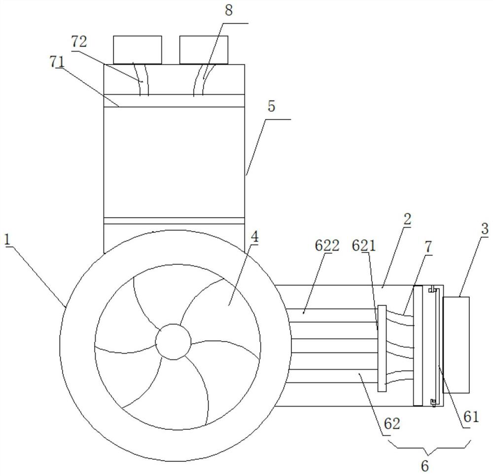
[0044] Such as Figure 1 A high-efficiency and wear-resistant sand suction pump, comprising: a pump body 1, a feed pipe 2, a front cover 3, a drive mechanism 4, a discharge pipe 5 and a filter mechanism 6, and the feed pipe 2 is arranged on the pump body 1 At the entrance of the pump body, the front end cover 3 is arranged at the front end of the feed pipe 2, the driving mechanism 4 is arranged inside the pump body 1, the discharge pipe 5 is arranged at the output end of the pump body 1, and the filter mechanism 6 It is arranged in the feed pipe 2, and a group of branch discharge pipes are arranged in the discharge pipe 5.

[0045] Wherein, a set of filter device 61 and adsorption assembly 62 are arranged in the filter mechanism 6, the filter device 61 is arranged at the feeding port and the discharge port of the feed pipe 2, and the adsorption assembly 62 is arranged at the feed pipe 2 inside, and the two are detachably connected.

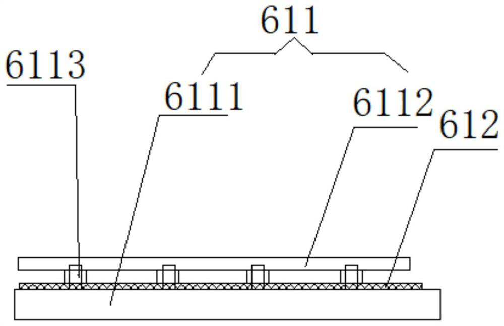
[0046] Further, the filter device 61 is p...


PUM


Abstract

The invention discloses a high-efficiency and wear-resistant sand suction pump, comprising: a pump body, a feeding pipe, a front end cover, a driving mechanism, a discharging pipe and a filtering mechanism, the feeding pipe is arranged at the inlet of the pump body, The front end cover is arranged at the front end of the feeding pipe, the driving mechanism is arranged inside the body, the discharge pipe is arranged at the output end of the pump body, the filter mechanism is arranged in the feeding pipe, and the discharge pipe There is a set of branch discharge pipes in it. The high-efficiency and wear-resistant sand suction pump described in the present invention can effectively filter out the impurities in the liquid entering the pump body by setting a filter mechanism, so as to avoid excessive impurities in the pump body and cause damage to the life of the pump body. It also effectively prevents its work efficiency from being affected by too many impurities in the pump body, and effectively improves its work efficiency. At the same time, the setting of the branch discharge pipe can play a role in shunting it to avoid It improves its work efficiency due to the liquid pressure caused by excessive power.

Description

technical field [0001] The invention belongs to the technical field of machinery, in particular to an efficient and wear-resistant sand suction pump and its working method. Background technique [0002] The sand suction pump is used to transport products that are corrosive to a certain extent and contain fine particles or crystallization media. Most of the existing sand suction pumps are conventional structures. However, in the actual use process, the water entering the pump body is often unable to be drained and discharged in time due to the excessive power output, resulting in the accumulation of liquid in the pump body. The circulation slows down, which affects its processing efficiency. At the same time, there will be some metal objects in the water. Once sucked into the pump body, it will scratch the inner wall of the pump body, which will affect the quality of the pump body and directly affect its use. Therefore, the existing sand suction pumps still need to be improv...

Claims


Application Information

Patent Timeline
Patent Type & Authority Patents(China)
IPC IPC(8): F04B15/02F04B53/20F04B53/16F04B53/22B01D36/00
CPCF04B15/02F04B53/20F04B53/16F04B53/22B01D36/00
Inventor 袁珩博
Owner 新沂市利源机械有限公司
Why Eureka
Try Eureka