Flat-plate evaporator optimized heat dissipation device

An evaporator and cover plate technology, which is applied to the field of optimized heat dissipation devices for flat plate evaporators, can solve the problems of reduced heat exchange performance of evaporators, long liquid replenishment paths of liquid absorbing wicks, and poor temperature uniformity of heat source surfaces, and achieves optimized heat exchange characteristics. , Improve the effect of uneven heat flow distribution and heat transfer characteristics

Active Publication Date: 2021-06-25
SHANGHAI JIAO TONG UNIV
View PDF8 Cites 0 Cited by
  • Summary
  • Abstract
  • Description
  • Claims
  • Application Information

AI Technical Summary

Problems solved by technology

The problem of this conventional structure plate evaporator lies in its one-way replenishment method, the liquid-absorbing core has a long replenishment path, the liquid-absorbing capacity is limited, and the problems such as uneven liquid distribution make the heat transfer coefficient and critical heat flux low, and the heat source surface uniform temperature The performance is poor, and it cannot be well applied to large-area and high-power heat source conditions
In addition, due to the direct connection between the liquid-absorbing core of the conventional structure and the liquid replacement chamber, the heat leaks into the compensation chamber through the base and the liquid-absorbing core, thereby increasing the temperature of the liquid in the chamber and reducing the heat transfer performance of the evaporator

Method used


Image

  • Flat-plate evaporator optimized heat dissipation device
  • Flat-plate evaporator optimized heat dissipation device
  • Flat-plate evaporator optimized heat dissipation device

Examples


Embodiment Construction

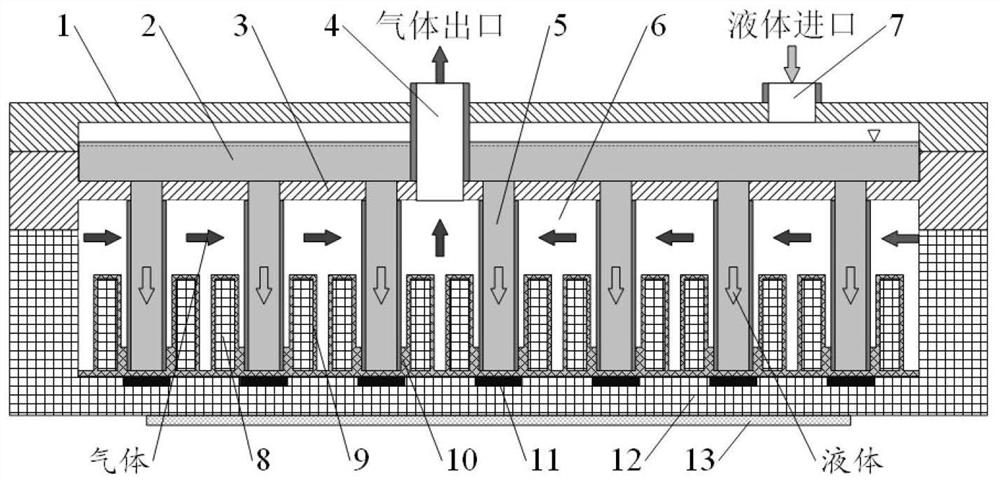
[0021] Such as figure 1 As shown, this embodiment relates to a flat-plate evaporator cooling device with a distributed liquid supply structure, including: a base 12, a housing composed of a gas-liquid chamber partition 3 and a cover plate 1, and a gas-liquid chamber arranged on the base 12. The evaporation gas chamber 6 between the chamber partitions 3, the liquid chamber 2 horizontally arranged between the gas-liquid chamber partition 3 and the cover plate 1, and several liquid supply conduits 5 vertically arranged in the gas-liquid chamber partition 3, Wherein: the liquid chamber 2 is in communication with the liquid supply conduit 5 and the housing is arranged on the heat source assembly 13 to be cooled, the liquid working medium at the outlet of the peripheral condensing equipment flows into the liquid chamber 2 through the liquid return pipe 7, and the working medium in the liquid chamber 2 It flows to the inner surface of the substrate 12 through the liquid supply condui...


PUM


Abstract

An optimized heat dissipation device for a flat-plate evaporator, including: a base, a gas-liquid chamber partition and a cover plate integrally packaged with a shell structure, the heating base is provided with a low thermal conductivity filler, and the cover plate is provided with an inlet for condensed return liquid and an outlet for evaporated gas , The liquid supply channel and the exhaust pipe are arranged on the separator of the gas-liquid chamber. Based on the structural requirements of the flat plate evaporator and the flow and heat transfer characteristic mechanism of the porous liquid-absorbing core, the invention realizes regional liquid replenishment by setting distributed liquid supply channels, reduces the uneven distribution of liquid, and improves the liquid-replenishment effect of the liquid-absorbing core. In addition, the partition design between the liquid suction core and the compensation chamber can effectively reduce the heat leakage problem in the traditional flat plate evaporator. The inner surface of the evaporator base is provided with a pin-fin structure, and the surface is sintered with particles to enhance the heat transfer characteristics. Under a variety of optimized structures, this kind of distributed flat-plate evaporator cooling device is preferably to effectively improve the heat transfer performance of the evaporator, and is suitable for large-area and high-power heat source requirements.

Description

technical field [0001] The invention relates to a technology in the field of radiators, in particular to an optimized heat dissipation device for a flat plate evaporator with a distributed liquid supply structure. Background technique [0002] Existing flat-plate evaporators are generally composed of evaporator shells, steam channels, liquid-absorbing cores, and liquid replenishing chambers. The heat source is located at the bottom of the evaporator, and the liquid-absorbing cores at the bottom absorb heat and evaporate quickly. After evaporation, the gas is discharged through the steam channels. The liquid in the rehydration cavity is absorbed by the liquid-absorbing core under capillary action, and is replenished near the heat source. The problem of this conventional structure plate evaporator lies in its one-way replenishment method, the liquid-absorbing core has a long replenishment path, the liquid-absorbing capacity is limited, and the problems such as uneven liquid di...

Claims


Application Information

Patent Timeline
Patent Type & Authority Patents(China)
IPC IPC(8): F28D15/04F28F3/02F28F9/00F28F13/18F28F21/08
CPCF28D15/04F28F3/022F28F9/002F28F13/185F28F21/083F28F21/084F28F21/085F28F21/086
Inventor 李健洪芳军张岩
Owner SHANGHAI JIAO TONG UNIV
Why Eureka
Try Eureka