Defect detection method and device based on rotary carrying table

A defect detection and stage technology, which is used in measurement devices, optical testing of flaws/defects, and material analysis by optical means. It can solve problems such as repeated scanning and adding optical systems to improve detection efficiency and imaging efficiency. , the effect of reducing the cost of optics

Pending Publication Date: 2020-09-25
WUHAN JINGLI ELECTRONICS TECH +1
View PDF12 Cites 16 Cited by
  • Summary
  • Abstract
  • Description
  • Claims
  • Application Information

AI Technical Summary

Problems solved by technology

In this way, the existing problem of needing repeated scanning or adding an optical system is solved, and at the same time, a more intelligent and higher-precision defect detection method and device are obtained

Method used


Image

  • Defect detection method and device based on rotary carrying table
  • Defect detection method and device based on rotary carrying table
  • Defect detection method and device based on rotary carrying table

Examples


Embodiment 1

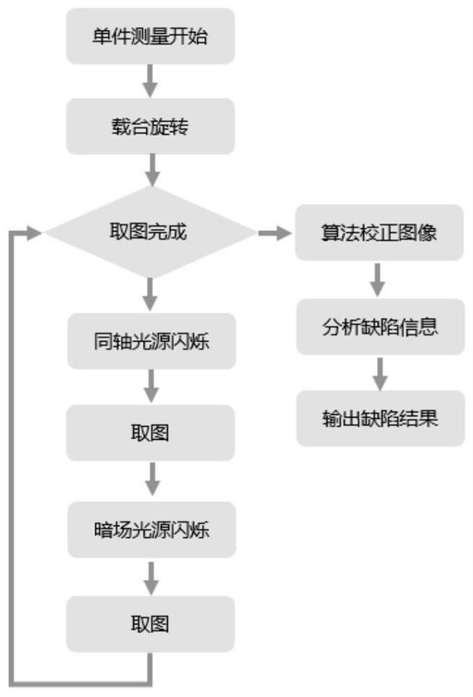
[0049] Embodiment 1 proposes a preferred defect detection method based on a rotating stage, the flow chart of which is as follows figure 1 As shown, when the single piece / one piece measurement starts, the stage starts to rotate, and the line scan camera is perpendicular to the direction of circular motion. When the test object passes the line scan camera, the bright field light source starts to flicker, and the line scan camera exposes the bright field image once , and then the dark-field light source starts to flicker, and the line-scan camera exposes the dark-field image once. Among them, the bright-field light source and the dark-field light source flash alternately, and the line-scan camera takes images of two different light sources respectively until the complete bright-field line-scan image and dark-field line-scan image of the object to be detected are respectively taken, Then the bright-field line-scan image and the dark-field line-scan image are spliced ​​to form a b...

Embodiment 2

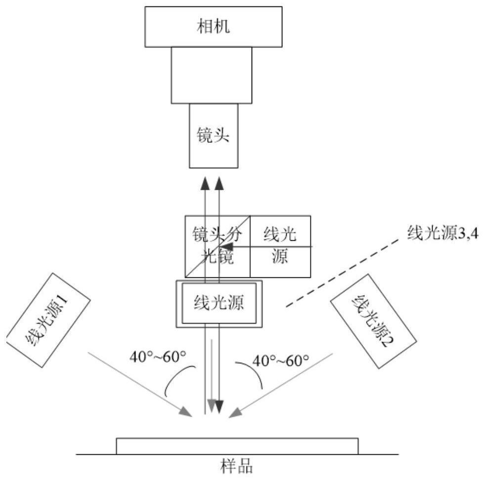
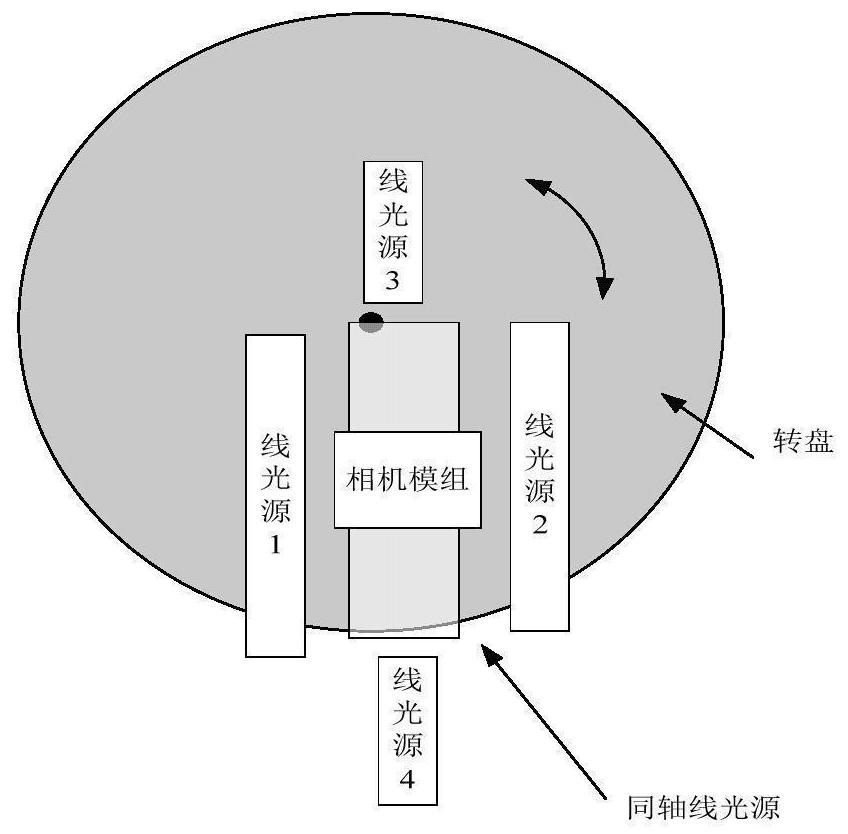
[0051] Embodiment 2 proposes a preferred defect detection device based on a rotating stage, such as figure 2 and image 3 As shown, the device includes a rotating stage, a line-scan camera, and a processing module. The rotary stage includes a turntable, a motor, and an encoder; the line-scan camera includes a lens and a camera, and the processing module includes a calculator module. Among them, the rotating stage drives the detection object / sample to make a circular motion; the line-scan camera is located above the rotation stage and the imaging direction is perpendicular to the direction of circular motion; the line-scan camera obtains the line-scan image of the detection object / sample; the processing module is based on the line-scan image Perform defect detection and obtain defect information.

[0052] The detection device also includes a fixing device, and the detection object is fixed by the fixing device. The fixing device may be a vacuum suction device, or any other ...


PUM


Abstract

The invention provides a defect detection method and device based on a rotary carrying table. The method comprises the steps that the rotary carrying table drives a detection object to do circular motion, wherein a line scanning camera is located above the rotary carrying table, and the imaging direction is perpendicular to the circular motion direction; the line scanning camera obtains a line scanning image of the detection object, and performs defect detection based on the line scanning image to obtain defect information. According to the invention, the line scanning camera is used for sampling and is matched with a stroboscopic light source, images can be sequentially illuminated by a stroboscopic bright field and a stroboscopic dark field in the scanning process, distortion correctionis carried out on the line scanning images acquired on the rotary carrying platform, defect detection is carried out on the corrected images, and defect characteristic information is output. Therefore, the defect problem that repeated scanning is needed or an optical system needs to be added in the prior art is solved, and meanwhile, the defect detection method and device which are more intelligent and higher in precision are obtained.

Description

technical field [0001] The invention relates to the field of automatic detection, in particular to a defect detection method based on a rotating carrier. Background technique [0002] At present, due to the limited space and many stations in the existing automatic inspection, the inspection equipment adopts a rotary layout. In the optical detection application of the rotating stage, one method uses an area array camera to take pictures, which specifically includes: stopping at intervals during the movement of the rotating stage, and using the area array camera to take pictures and collect inspection images. The other uses a line-scan camera to take pictures, which specifically includes: rotating the stage to transport the product to the line-scan camera station, and then using the line-scan camera to perform linear line-scanning to obtain inspection images; among them, the line-scan cameras are all under the LED backlight Under the environment, the information is obtained a...

Claims


Application Information

Patent Timeline
Patent Type & Authority Applications(China)
IPC IPC(8): G01N21/88G01N21/956
CPCG01N21/8851G01N21/8806G01N21/956
Inventor 邓怀波梁晓捷高书伟康强强
Owner WUHAN JINGLI ELECTRONICS TECH
Why Eureka
Try Eureka