
Transformer processing equipment

A technology for processing equipment and transformers, which is applied in the field of transformers and can solve problems such as deformation of the transformer shell and burning of internal electronic components

Inactive Publication Date: 2020-09-25
刘美阳
View PDF0 Cites 3 Cited by
  • Summary
  • Abstract
  • Description
  • Claims
  • Application Information

AI Technical Summary

Problems solved by technology

[0003] The present invention aims to solve the technical problem that when the transformer processing equipment is drying the transformer shell, the internal heat is too high due to the untimely discharge of heat, so that the transformer shell is deformed and the internal electronic components are burned.

Method used


Image

  • Transformer processing equipment
  • Transformer processing equipment
  • Transformer processing equipment

Examples


Embodiment Construction

[0029] as attached figure 1 to attach Figure 6 Shown:

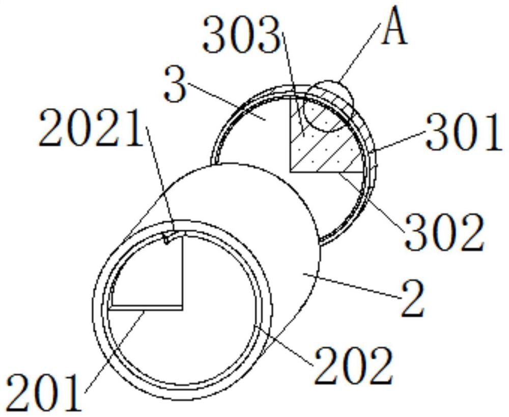
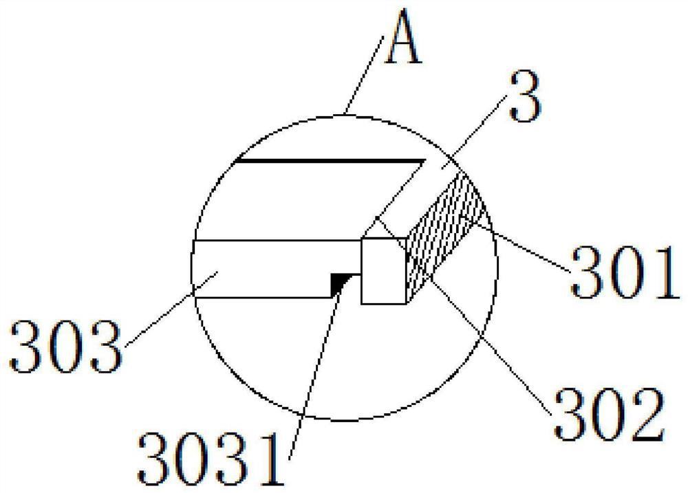
[0030] The present invention provides a transformer processing equipment, comprising a main body 1, an exhaust shaft 2 and a piston plate 3, the top of the main body 1 is fixedly connected with the exhaust shaft 2, and the middle part of the exhaust shaft 2 is embedded with a piston plate 3;

[0031] The main body 1 includes a cavity 101 and a transport frame 102, the cavity 101 is opened in the middle of the body 1, and the transport frame 102 is embedded in the bottom of the cavity 101;

[0032] The exhaust shaft 2 includes an exhaust port 201, a rotating shaft 202, a fitting groove 203 and an offset block 204. The exhaust port 201 is opened on the bottom side of the exhaust shaft 2, and the rotating shaft 202 is embedded in the exhaust shaft. 2 Around the inner middle part, the opening of the fitting groove 203 is arranged around the bottom end of the inner middle part of the exhaust shaft 2, and the offset block 20...


PUM


Abstract

The transformer processing equipment comprises a main body, an exhaust shaft and a piston plate, the exhaust shaft is fixedly connected to the top end of the main body, and the piston plate is embedded in the middle of the interior of the exhaust shaft; the main body comprises a cavity and a conveying frame; the exhaust shaft comprises an exhaust port, a rotating shaft, an embedding groove and anoffset block; the rotating shaft comprises an impact block and an embedding ring; the piston plate comprises a rotary groove mark, a displacement groove, a displacement plate and a transmission ring;the displacement groove comprises a reset groove, and the displacement plate comprises an offset groove. The device is provided with a piston plate, and the piston plate is driven to ascend and descend to suck and discharge a large amount of heat in the main body according to a certain rule, so that the internal heat is controlled to prevent the internal temperature of the device from being too high.

Description

technical field [0001] The invention relates to the technical field of transformers, more specifically, to a transformer processing equipment. Background technique [0002] Transformer is a device that uses the principle of electromagnetic induction to change AC voltage. The main components are primary coil, secondary coil and iron core. The main functions are: voltage conversion, current conversion, impedance conversion, isolation, voltage stabilization, etc. However, in the existing transformer processing steps, it is necessary to dry the painted shell, and when drying, the internal heat will rise rapidly because of its internal closure, and the heat is discharged through its certain The measured emission makes the internal heat still difficult to control. When the heat is too high and cannot be discharged in time, it will easily lead to deformation of the shell and burning of internal electronic components. Contents of the invention [0003] The invention aims to solv...

Claims


Application Information

Patent Timeline
Patent Type & Authority Applications(China)
IPC IPC(8): H01F41/00B05D3/04
CPCB05D3/0413H01F41/00
Inventor 刘美阳
Owner 刘美阳
Learn More