
Long-distance power supply network

A power supply network, long-distance technology, applied in the direction of electrical components, circuit devices, etc., can solve the problems of line loss, base station power finding, large investment, etc., and achieve the effect of reducing energy consumption

Pending Publication Date: 2020-09-25
BEIJING INVISPOWER TECH CO LTD
View PDF0 Cites 0 Cited by
  • Summary
  • Abstract
  • Description
  • Claims
  • Application Information

AI Technical Summary

Problems solved by technology

However, with the rapid development of communication technology, from 4G to 5G, the layout density of base stations has been greatly expanded, and the power consumption of the system has also increased several times. There are problems in the coordination and communication in the early stage and the maintenance and management in the later stage, which cannot meet the needs of the rapid development of base station construction
[0003] In addition, the power supply of the base station also has a remote power supply method by the communication enterprise itself, including DC remote power supply and AC remote power supply, but it is necessary to erect a special cable for AC and DC power transmission, and the power supply cable is laid outdoors for a long distance, which not only has line loss , there are also issues such as personal safety, electrical safety and anti-theft
At the same time, as the construction of communication networks continues to extend to remote areas, the quality of outdoor power supply is particularly poor, and even where there is no mains power, the problem of power supply for base stations is more prominent, and high-quality power supply is the key to reliable operation of network communication equipment

Method used


Image

  • Long-distance power supply network
  • Long-distance power supply network
  • Long-distance power supply network

Examples


Embodiment Construction

[0026] Embodiments of the present invention are described in detail below, examples of which are shown in the drawings, wherein the same or similar reference numerals designate the same or similar elements or elements having the same or similar functions throughout. The embodiments described below by referring to the figures are exemplary only for explaining the present invention and should not be construed as limiting the present invention.

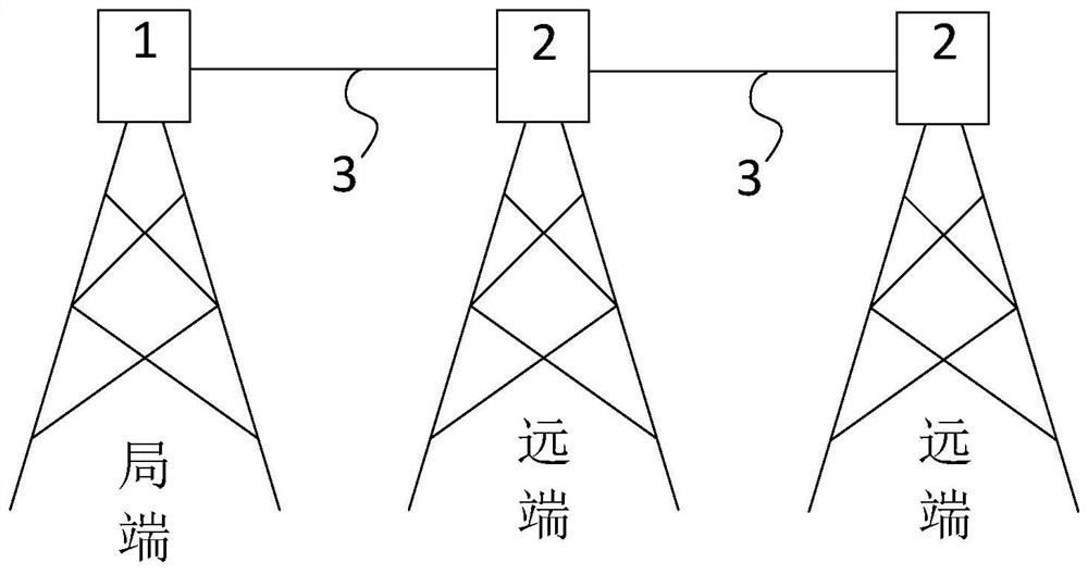
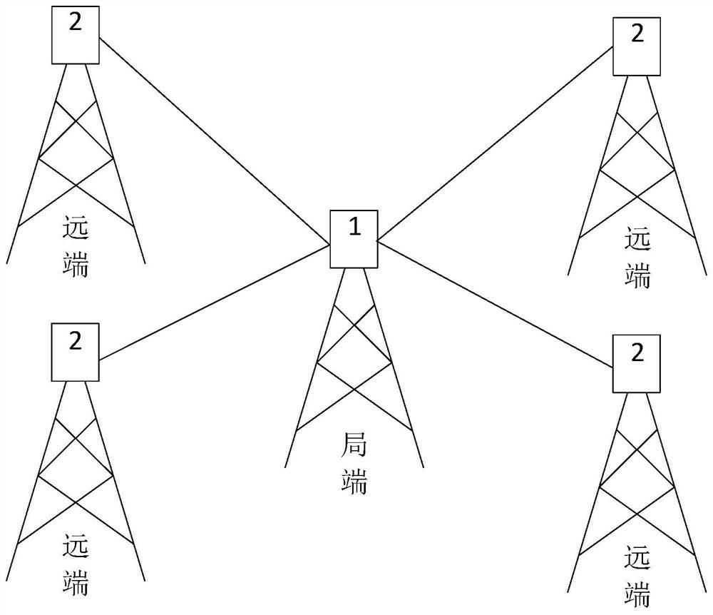
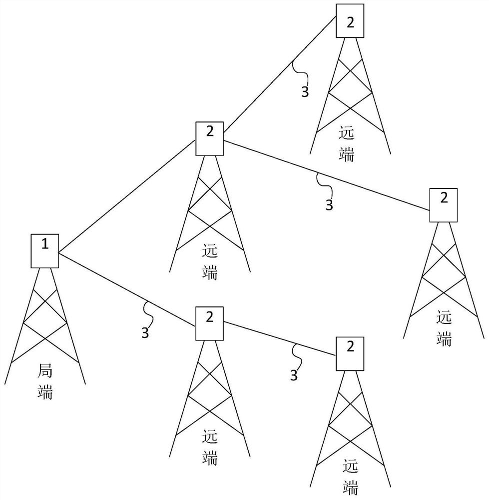
[0027] The invention discloses a long-distance power supply network, see Figure 1A , Figure 1B and Figure 1C , has a plurality of power consumption terminals, among these power consumption terminals, at least one serves as the local end, and the others serve as remote ends. There is a central equipment 1 on the central office, and a remote equipment 2 on the far end, and a plurality of power terminals are communicated through guide cables 3 . The significant difference between the central end and the remote end is that the central e...


PUM


Abstract

The invention discloses a long-distance power supply network, which is provided with a plurality of power utilization terminals. At least one of the plurality of power utilization terminals is used asa local side, and other power utilization terminals are used as far sides. The local side is provided with local side equipment, the far end is provided with far end equipment, and the plurality of power utilization terminals are communicated through guide cables. The local side equipment comprises a power supply, a first working circuit, a first coil and a second coil. The first working circuitis communicated with the first coil, the first coil is coupled with the second coil, and the number of turns of the second coil is greater than that of the first coil. The far-end device comprises a load, a second working circuit, a third coil and a fourth coil. The second working circuit is communicated between the load and the third coil, the third coil is coupled with the fourth coil, and the number of turns of the fourth coil is larger than that of the third coil. According to the long-distance power supply network, on the basis of realizing long-distance power supply, the energy loss is reduced.

Description

technical field [0001] The invention relates to long-distance power supply networks. Background technique [0002] As an important infrastructure in communication and other fields, base station construction will be in a stage of rapid development for a long time. Conventional power supply methods for communication base stations generally include direct power supply from the power supply bureau and transfer power supply from surrounding enterprises. However, with the rapid development of communication technology, from 4G to 5G, the layout density of base stations has been greatly expanded, and the power consumption of the system has also increased several times. There are problems in the coordination and communication in the early stage and the maintenance and management in the later stage, which cannot meet the needs of the rapid development of base station construction. [0003] In addition, the power supply of the base station also has a remote power supply method by the...

Claims


Application Information

Patent Timeline
Patent Type & Authority Applications(China)
IPC IPC(8): H02J50/12H02J50/40H02J50/50
CPCH02J50/12H02J50/40H02J50/50H02J50/502
Inventor 王哲陆钧贺凡波葛俊杰马俊超
Owner BEIJING INVISPOWER TECH CO LTD
Learn More