Cooking device

A cooking device and driving device technology, applied in the direction of food science, etc., can solve problems such as material caking, achieve the effects of improving utilization efficiency, preventing caking, and reducing energy consumption

Pending Publication Date: 2020-09-29
烟台良荣机械精业有限公司
0 Cites 0 Cited by

AI-Extracted Technical Summary

Problems solved by technology

[0005] The main purpose of the present invention is to provide a cooking device, which can reduce the condensed water produced b...

Method used

In order to drive the barrel body 20 to turn around, the cooking device in the present embodiment also includes a driving device 50, which is driven and connected to the barrel body 20, so as to be convenient to drive the barrel body 20 to turn around to fully carry out the food materials in the barrel body 20. Cook. Preferably, the driving device 50 in this embodiment is a driving motor. During installation, the first side of the barrel body 20 is installed on the bracket 10 through the support shaft 60, the second side of the barrel body 20 is installed on the bracket 10 through the sliding bearing seat 70, the drive motor is docked with the support shaft 60, and the drive motor rotates. It can drive the support shaft 60 to rotate, and then drive the barrel body 20 to rotate, the structure is simple and easy to realize.
In the present embodiment, the inner tub 21 is provided with a steam heating tube assembly 40 which is independent of the inner tub 21, and the steam heating tube assembly 40 is connected with the steam inlet, so as to facilitate delivery of steam to the inner tub 21, thereby facilitating the heating of the inner tub 21. Foodstuffs are steamed. The setting independent of the inner tub 21 here means that the steam heating tube assembly 40 will not move with the rotation of the inner tub 21, and the stationary steam heating tube assembly 40 can evenly deliver steam to the inner tub 21 during the rotation of the inner tub 21 The ingredients in the container are convenient for evenly cooking the ingredients.
[0031] Preferably, the preheating pipe 30 in this embodiment is arranged in close contact with the outer wall surface of the inner barrel 21, so that the heat carried by the steam inside the preheating pipe 30 can be quickly transferred to the inner barrel 21. In the actual design process, the end of the preheating pipeline 30 in this embodiment is provide...

Abstract

The present invention provides a cooking device. The cooking device comprises a support, a barrel body, and a preheating pipeline, wherein a steam inlet is formed in the support; the barrel body is rotatably installed on the support and comprises an inner barrel and an outer sleeve, the outer sleeve is arranged on the periphery of the inner barrel in a sleeving mode, and a cavity is defined by theouter sleeve and the inner barrel; the preheating pipeline is arranged in the cavity and communicates with the steam inlet so as to preheat the interior of the barrel body. Due to the fact that the preheating pipeline is arranged in the cooking device, during actual work, food materials are placed in the inner barrel firstly, then steam can be conveyed into the preheating pipeline under the action of the preheating pipeline, and the inner barrel is preheated through the preheating pipeline; after the inner barrel is preheated to a certain temperature, the steam is introduced into the inner barrel to cook the food materials in the inner barrel, so that the food materials in the inner barrel are prevented from generating condensed water when the steam enters the inner barrel without being preheated, and the caking phenomenon of the food materials is further prevented.

Application Domain

Food science

Technology Topic

PhysicsCondensed water +5

Image

  • Cooking device
  • Cooking device

Examples

  • Experimental program(1)

Example Embodiment

[0023] It should be noted that, in the case of no conflict, the embodiments in the present application and the features in the embodiments can be combined with each other. The present invention will be described in detail below with reference to the accompanying drawings and examples.
[0024] It should be noted that the terminology used here is only used to describe specific implementations, and is not intended to limit the exemplary implementations according to the present application. As used herein, unless the context clearly dictates otherwise, the singular is intended to include the plural, and it should also be understood that when the terms "comprising" and/or "comprising" are used in this specification, they mean There are features, steps, operations, means, components and/or combinations thereof.
[0025] For the convenience of description, spatially relative terms may be used here, such as "on ...", "over ...", "on the surface of ...", "above", etc., to describe the The spatial positional relationship between one device or feature shown and other devices or features. It will be understood that the spatially relative terms are intended to encompass different orientations of the device in use or operation in addition to the orientation depicted in the figures. For example, if the device in the figures is turned over, devices described as "above" or "above" other devices or configurations would then be oriented "beneath" or "above" the other devices or configurations. under other devices or configurations". Thus, the exemplary term "above" can encompass both an orientation of "above" and "beneath". The device may be otherwise oriented (rotated 90 degrees or at other orientations) and the spatially relative descriptions used herein interpreted accordingly.
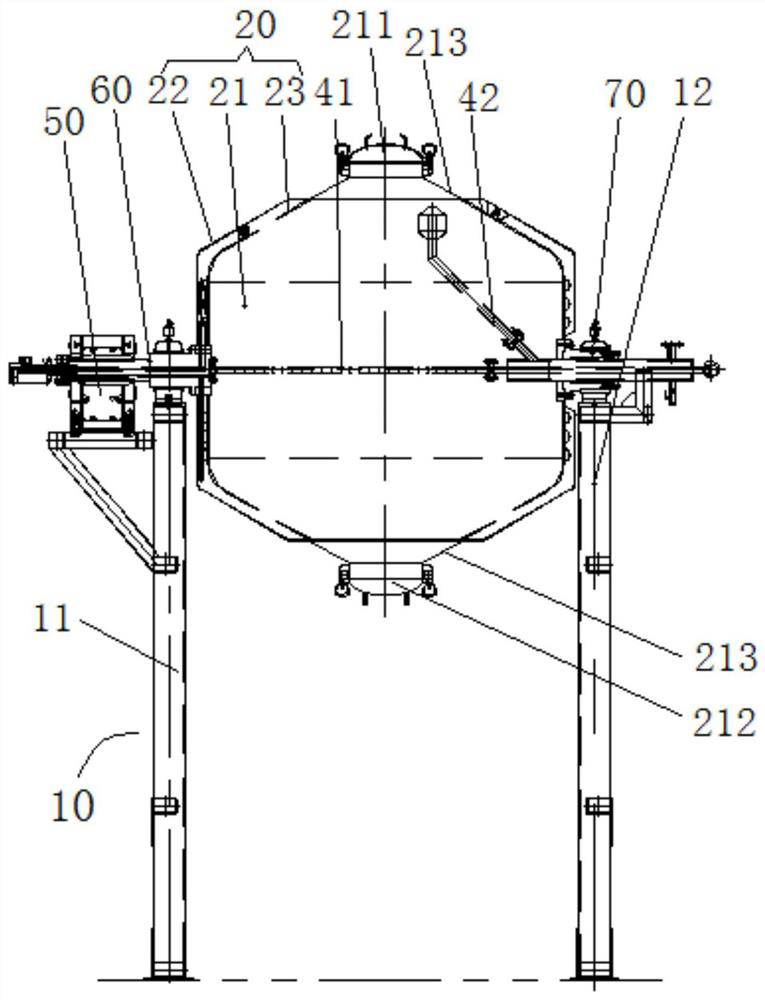
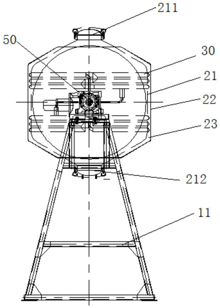
[0026] see Figure 1 to Figure 2 As shown, according to the embodiment of the present invention, a cooking device is provided, which includes a support 10 , a barrel body 20 and a preheating pipeline 30 .
[0027] Wherein, the bracket 10 is provided with a steam inlet (not shown in the figure); the barrel body 20 is rotatably installed on the bracket 10, the barrel body 20 includes an inner barrel 21 and an outer casing 22, and the outer casing 22 is sleeved on the outer periphery of the inner barrel 21, and A cavity 23 is formed around the inner barrel 21; a preheating pipe 30 is arranged in the cavity 23, and the cavity 23 is filled with fillers, and the preheating pipe 30 communicates with the steam inlet to preheat the inside of the barrel 20.
[0028] Since the cooking device in this embodiment is provided with a preheating pipeline 30, in actual work, the food material is first placed in the inner barrel 21, and then the steam can be transported into the preheating pipeline 30 through the function of the preheating pipeline 30, The inner barrel 21 is preheated through the preheating pipeline 30. After the inner barrel 21 is preheated to a certain temperature, steam is passed into the inner barrel 21 to cook the ingredients in the inner barrel 21 to prevent the ingredients in the inner barrel 21 from being preheated. When the steam enters, condensed water is generated to prevent the food from caking. After the cooking is completed, the overcoat 22 can also keep the inner barrel 21 warm.
[0029] It can be seen that the cooking device of the present invention will not form condensed water in the food during the preheating process of the inner tub 21 . After the preheating is completed, the steam in the inner barrel 21 can be used to cook and mature the food. The cavity 23 and the preheating pipe 30 in the present invention have the function of preheating and heat preservation, which improves the utilization efficiency of steam and reduces energy consumption.
[0030] Preferably, the preheating pipeline 30 in this embodiment is a coiled tube arranged around the outer circumference of the inner tub 21 , so as to facilitate sufficient and rapid preheating of the inner tub 21 .
[0031] Preferably, the preheating pipe 30 in this embodiment is arranged adjacent to the outer wall surface of the inner tub 21 , so as to quickly transfer the heat carried by the steam inside the preheating pipe 30 to the inner tub 21 . In the actual design process, the end of the preheating pipeline 30 in this embodiment is provided with a control valve. After the preheating is completed, it is convenient to discharge the condensed water in the preheating pipeline 30 to avoid condensed water remaining in the preheating pipeline. , in the process of heating the foodstuffs in the inner barrel 21, heat is absorbed to cause waste of heat.
[0032] In this embodiment, the inner tub 21 is provided with a steam heating pipe assembly 40 which is independent of the inner tub 21. The steam heating pipe assembly 40 is connected to the steam inlet, so as to facilitate the delivery of steam into the inner tub 21, thereby facilitating the steaming of food materials in the inner tub 21. . The setting independent of the inner tub 21 here means that the steam heating tube assembly 40 will not move with the rotation of the inner tub 21, and the stationary steam heating tube assembly 40 can evenly deliver steam to the inner tub 21 during the rotation of the inner tub 21 The ingredients in the container are convenient for evenly cooking the ingredients.
[0033] Specifically, the steam heating pipe assembly 40 in this embodiment includes an intake pipe 41 and an exhaust pipe 42, the intake pipe 41 extends along the axial direction of the inner tub 21, the exhaust pipe 42 is obliquely connected to the intake pipe 41, and the exhaust The outlet end of the pipe 42 is located above the intake pipe 41 . Through the function of the air inlet pipe 41, it is convenient to transport the steam to the center of the inner barrel 21, so that the ingredients in the inner barrel 21 can be evenly cooked;
[0034] See you again figure 1 and figure 2 As shown, the bracket 10 in this embodiment includes a first side frame 11 and a second side frame 12 arranged at intervals. During installation, the bucket body 20 is rotatably installed between the first side frame 11 and the second side frame 12 . Of course, in other embodiments of the present invention, the first side frame 11 and the second side frame 12 of the bracket 10 can also be set as an integrated structure, instead of two independent side frames, as long as it is within the concept of the present invention The following other deformation methods are all within the protection scope of the present invention.
[0035] In order to drive the barrel body 20 to rotate, the cooking device in this embodiment further includes a driving device 50, which is drivingly connected to the barrel body 20, so as to drive the barrel body 20 to rotate to fully cook the ingredients in the barrel body 20. Preferably, the driving device 50 in this embodiment is a driving motor. During installation, the first side of the barrel body 20 is installed on the bracket 10 through the support shaft 60, the second side of the barrel body 20 is installed on the bracket 10 through the sliding bearing seat 70, the drive motor is docked with the support shaft 60, and the drive motor rotates. It can drive the support shaft 60 to rotate, and then drive the barrel body 20 to rotate, the structure is simple and easy to realize.
[0036]The two ends of the inner barrel 21 in this embodiment are respectively provided with a material inlet 211 and a material outlet 212, and the connection line between the material inlet 211 and the material outlet 212 is perpendicular to the rotation axis of the inner barrel 21, which is convenient for avoiding the driving of the cooking device. device 50. Both ends of the inner barrel 21 are provided with a tapered structure 213, and the feed port 211 and the discharge port 212 are respectively arranged at the tip of the two tapered structures 213, which is convenient for putting materials into the inner barrel 21, and is convenient for putting the inner barrel 21 The ingredients of the food are completely discharged from the inner bucket 21.
[0037] According to the above-mentioned structure, it can be known that the bracket 10 of the cooking device of the present invention supports and fixes the above-mentioned other parts, and has mechanical properties such as strength and rigidity required to ensure stable operation of the equipment.
[0038] The drive motor is the power source for the barrel body 20 to perform the rotary motion.
[0039] One end of the support shaft 60 is connected with the barrel body 20 , the other end of the barrel body 20 is connected with the sliding bearing seat 70 , and the support shaft 60 is assembled in the bearing fixed on the bracket 10 . When connecting, the coaxiality tolerance of the support shaft is within a reasonable range to ensure the smooth execution of the rotary motion. The axis of the support shaft 60 is coplanar with the centerline of rotation of the barrel body 20 and is perpendicular to each other through its midpoint. A heating medium passes through the support shaft 60, and the seals are reliable everywhere.
[0040] The shape of the barrel body 20 in the present invention is in the shape of a waist drum. When rotating around the axis of the support shaft 60, the space at the bottom of the barrel body 20 is constantly changing, causing the material to turn irregularly, so as to destroy the formed material mass. The manholes at both ends of the barrel body 20 serve as the material inlet 211 and the material outlet 212, and a reasonable switching sequence ensures that the material goes in and out smoothly and protects the operator. The preheating pipeline 30 is arranged around the outer circumference of the inner barrel 21, and utilizes the principle of heat conduction to raise the product temperature of the material. Insulation material is added in the cavity 23 between the inner tub 21 and the outer jacket 22 to protect the environment in the inner tub 21 favorably. The steam heating pipe assembly 40 guides the working steam into the inner barrel 21 to directly process the materials.
[0041] From the above description, it can be seen that the above-mentioned embodiments of the present invention have achieved the following technical effects:
[0042] The cooking device of the present invention is a process equipment capable of reducing the amount of condensed water generated and avoiding the occurrence of material agglomeration during the cooking process. When working, when the material is put into the inner barrel, the material is indirectly heated by the principle of heat conduction, and no condensed water is formed in the material during this process. After the preheating is completed, steam is passed through the barrel to cook the material. During this process, the heat preservation function of the cavity of the barrel improves the utilization efficiency of steam and reduces energy consumption.
[0043] It should be noted that the terms "first" and "second" in the description and claims of the present application and the above drawings are used to distinguish similar objects, but not necessarily used to describe a specific sequence or sequence. It is to be understood that the data so used are interchangeable under appropriate circumstances such that the embodiments of the application described herein, for example, can be practiced in sequences other than those illustrated or described herein. Furthermore, the terms "comprising" and "having", as well as any variations thereof, are intended to cover a non-exclusive inclusion, for example, a process, method, system, product or device comprising a sequence of steps or elements is not necessarily limited to the expressly listed instead, may include other steps or elements not explicitly listed or inherent to the process, method, product or apparatus.
[0044] The above descriptions are only preferred embodiments of the present invention, and are not intended to limit the present invention. For those skilled in the art, the present invention may have various modifications and changes. Any modifications, equivalent replacements, improvements, etc. made within the spirit and principles of the present invention shall be included within the protection scope of the present invention.

PUM

no PUM

Description & Claims & Application Information

We can also present the details of the Description, Claims and Application information to help users get a comprehensive understanding of the technical details of the patent, such as background art, summary of invention, brief description of drawings, description of embodiments, and other original content. On the other hand, users can also determine the specific scope of protection of the technology through the list of claims; as well as understand the changes in the life cycle of the technology with the presentation of the patent timeline. Login to view more.

Similar technology patents

Microbial fermentation feeding and stirring device

InactiveCN111187706AIncrease the mixing areaavoid caking
Owner:JIANGSU UNISON BIOTECH DEV

Anti-caking method for powder ash pot

InactiveCN105270776Aincrease mobilityavoid caking
Owner:HICO PETRO TECH

Flue gas filtering device

PendingCN113350904Aavoid cakingavoid clogging
Owner:SUZHOU XIRE ENERGY SAVING ENVIRONMENTAL PROTECTION TECH CO LTD +1

Reaction kettle for titanium dioxide processing

PendingCN113941407Aavoid caking
Owner:HUNAN CHUANGDA YUTU CHEM CO LTD

Crayfish dried meat floss and preparation method thereof

PendingCN111264797AEnzyme hydrolysisavoid caking
Owner:JIANGSU AGRI ANIMAL HUSBANDRY VOCATIONAL COLLEGE

Classification and recommendation of technical efficacy words

  • avoid caking
  • Improve utilization efficiency

Crushing system for cellulose ether production raw materials

ActiveCN111229369Anovel structureavoid caking
Owner:浙江海申新材料有限公司

Argil-grease blending tank

InactiveCN103691348Awell mixedavoid caking
Owner:CHONGQING JIDING FOOD

Pretreatment equipment for extracting sargassum fusiforme dietary fiber

PendingCN111296853Aavoid caking
Owner:MARINE FISHERIES RES INST OF ZHEJIANG

Outdoor automatic fire extinguishing electric meter box

InactiveCN112505382Aavoid caking
Owner:HANGZHOU SANWO INTELLIGENT TECH CO LTD

Charging method for mobile robot in wireless charging sensor network system

ActiveCN105896672AImprove utilization efficiencyNetwork Energy Consumption Balance
Owner:HOHAI UNIV CHANGZHOU

Solar cell packaging adhesive film with high light conversion efficiency

ActiveCN104927686AImprove utilization efficiencygood light stability
Owner:HANGZHOU FIRST APPLIED MATERIAL CO LTD
Why Eureka
Try Eureka