Oil mist collecting and filtering device for oiling machine

A filter device and oiler technology, which is applied to spray devices, dispersed particle filtration, gas treatment, etc., can solve the problems of surrounding equipment pollution, oil mist drifting, and cleaning difficulties, and achieve improved surface quality, reduced impact, and improved operation. effects of the environment

Inactive Publication Date: 2020-09-29
BAOSHAN IRON & STEEL CO LTD
View PDF9 Cites 0 Cited by
  • Summary
  • Abstract
  • Description
  • Claims
  • Application Information

AI Technical Summary

Problems solved by technology

[0005] In view of the above-mentioned defects existing in the prior art, the object of the present invention is to provide an oil mist collecting and filtering device for an oiler, which effectively solves the problem that the oil mist drifts from the outlet side of the oiler, causing the ground and surrounding equipment to be covered with oil. Liquid contamination, difficult to clean up

Method used


Image

  • Oil mist collecting and filtering device for oiling machine
  • Oil mist collecting and filtering device for oiling machine
  • Oil mist collecting and filtering device for oiling machine

Examples


Embodiment Construction

[0027] The technical solutions of the present invention will be further described below in conjunction with the accompanying drawings and embodiments.

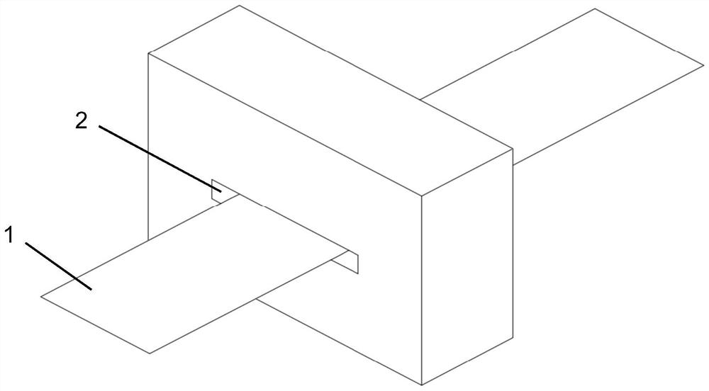
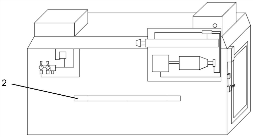
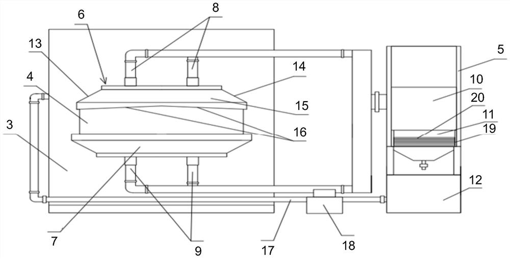
[0028] Please combine Figure 3 to Figure 5 As shown, an oil mist collection and filtering device for oiler provided by the present invention is arranged on the outlet side 4 of the oiler 3 on the oiler 3 and includes an oil suction device arranged on the outlet side 4 of the oiler Cover structure, and the oil collection tank 5 that communicates with the oil suction cover structure through the oil pipe structure.

[0029] Preferably, the oil suction cover structure includes an upper oil suction cover 6 arranged above the outlet side 4 of the oiler, and a lower oil suction cover 7 below the outlet side 4 of the oiler.

[0030] Preferably, the oil pipe structure includes an upper oil suction pipe 8 connected to the upper oil suction cover 6 and a lower oil suction pipe 9 connected to the lower oil suction cover 7 .

[0031] Pr...


PUM


Abstract

The invention discloses an oil mist collecting and filtering device for an oiling machine. The device is arranged on the outlet side of the oiling machine and comprises an oil suction hood structure arranged on the outlet side of the oiling machine and an oil collecting tank communicated with the oil suction hood structure through an oil pipe structure; and the oil suction hood structure comprisesan upper oil suction hood arranged above the outlet side of the oiling machine and a lower oil suction hood arranged below the outlet side of the oiling machine. The oil pipe structure comprises an upper oil suction pipe connected to the upper oil suction hood and a lower oil suction pipe connected to the lower oil suction hood. A fan device, a filtering device and an oil collecting tank are sequentially arranged in the oil collecting tank from top to bottom; and the upper oil suction pipe and the lower oil suction pipe are both connected with the fan device. The problems that oil mist driftsaway from the outlet side of an oiling machine, the ground and surrounding equipment are polluted by oil liquid, and the cleaning is difficult are solved.

Description

technical field [0001] The invention relates to electrostatic oiler equipment, in particular to an oil mist collecting and filtering device for the oiler. Background technique [0002] The existing electrostatic oiler is mainly composed of an oiling room, a high-voltage electrostatic power source, an oil supply system, a refueling heating cycle system, an electric control system, and an operating table. The upper and lower oiling knife beams / nozzles are installed horizontally in the oiling room , the steel plate can freely pass through it, and the oil supplied quantitatively by the oil supply system to the oiled knife beam / nozzle flows out evenly from the knife edge slit of the oiled knife beam / nozzle. The high-voltage electrostatic power supply outputs about 100KV negative DC high voltage, which is added to the oiled knife beam / nozzle, so that a high-voltage electrostatic field is generated between the oiled knife beam / nozzle and the steel plate as the bottom plate. The ne...

Claims


Application Information

Patent Timeline
Patent Type & Authority Applications(China)
IPC IPC(8): B01D46/10B05B14/00
CPCB01D46/10B01D2258/02B05B14/00
Inventor 吴鹏徐争光王木贾卫国刘倪俊牟战旗
Owner BAOSHAN IRON & STEEL CO LTD
Why Eureka
Try Eureka