Transceiver assembly positioning tool

A technology for sending and receiving components and positioning tooling, which is applied in auxiliary devices, manufacturing tools, metal processing, etc., can solve problems such as troublesome positioning operations, affecting welding quality, and uneven and sufficient melting of solder paste, etc., to achieve high positioning effect, The effect of easy operation

Pending Publication Date: 2020-09-29
WUXI HUACE ELECTRONICS SYST
View PDF0 Cites 1 Cited by
  • Summary
  • Abstract
  • Description
  • Claims
  • Application Information

AI Technical Summary

Problems solved by technology

The positioning tool in the prior art has poor positioning effect, and the positioning operation is more troublesome. In addition, because of the positioning tool, it is easy to cause uneven heating of the components, and the melting of the solder paste cannot be uniform and fully melted, which affects the welding quality

Method used


Image

  • Transceiver assembly positioning tool
  • Transceiver assembly positioning tool
  • Transceiver assembly positioning tool

Examples


Embodiment Construction

[0018] The specific implementation manner of the present invention will be described below in conjunction with the accompanying drawings.

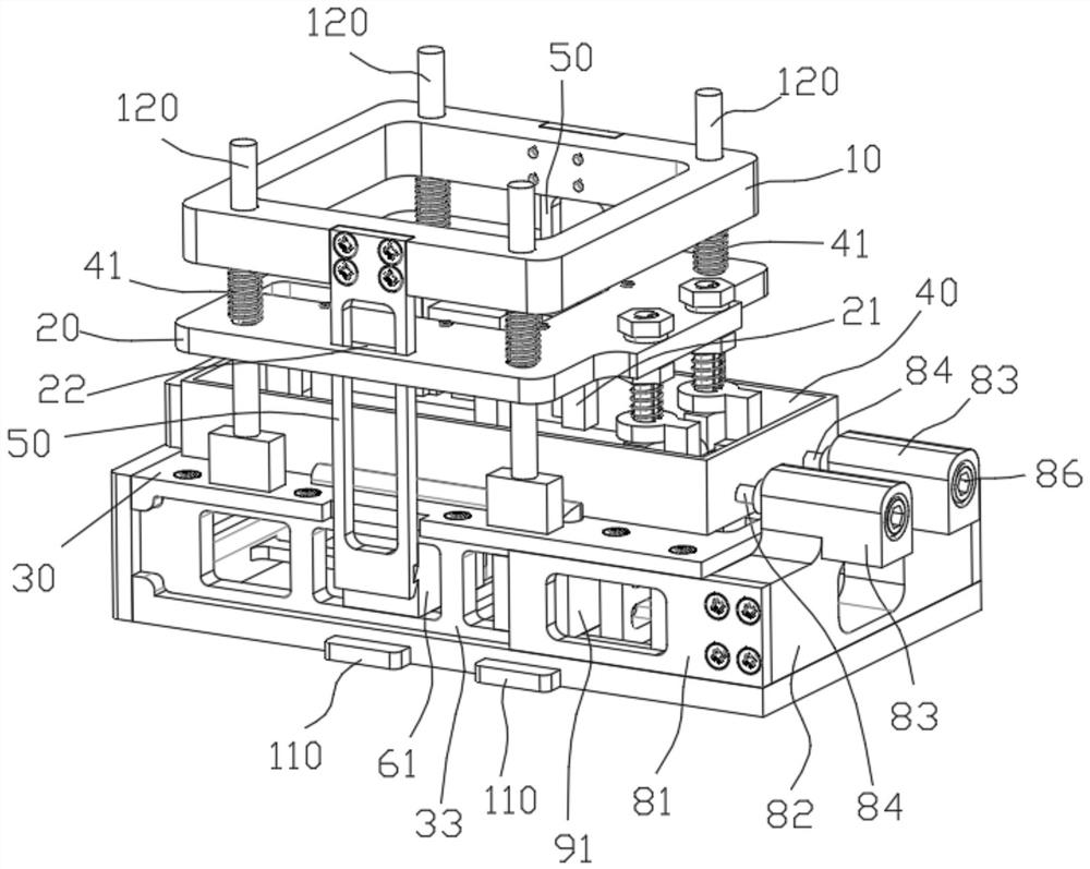
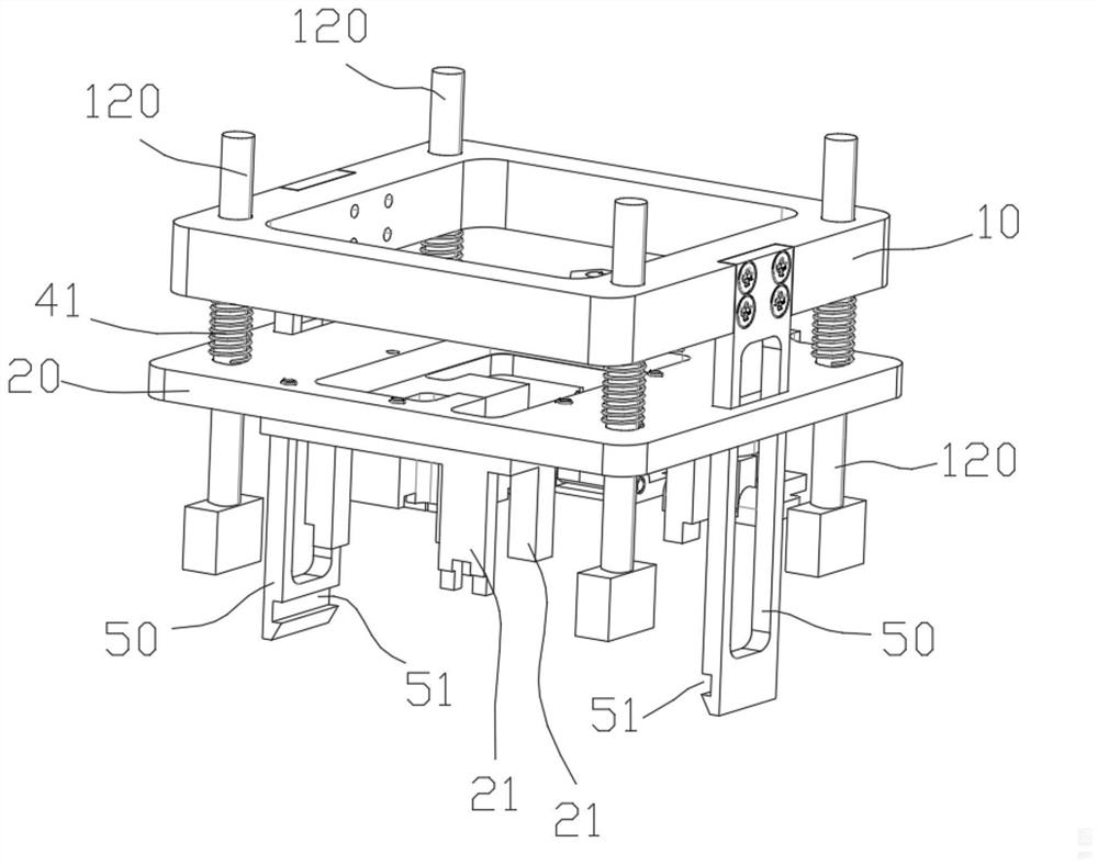
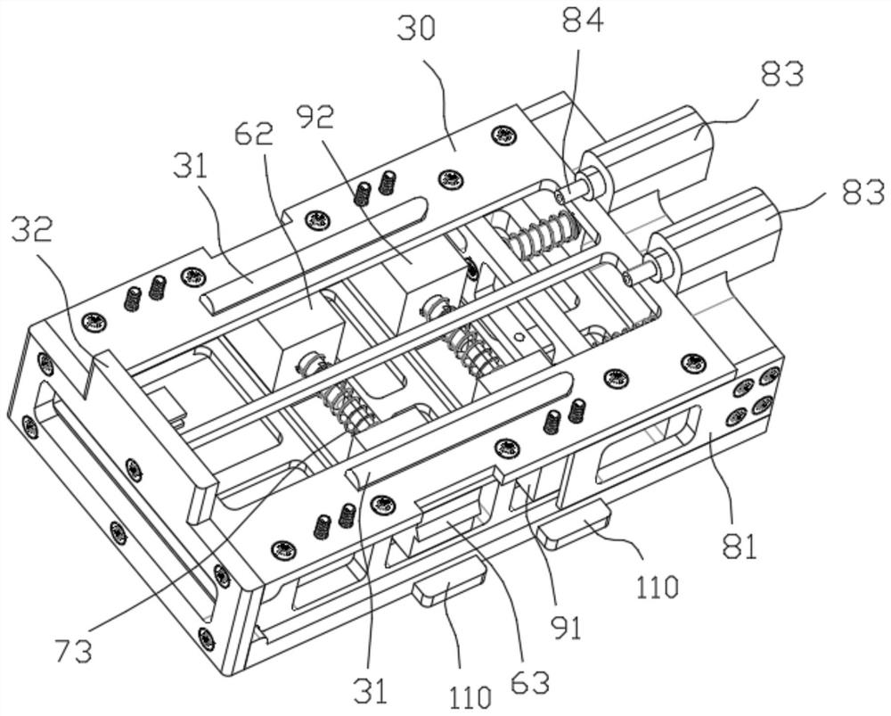
[0019] Such as Figure 1-6 As shown, the positioning tooling of the transceiver assembly of this embodiment includes an upper press frame 10, a lower press frame 20, a frame-like base 30 and a box body 40 of the transceiver assembly. The components are placed inside the box body 40, and the box body 40 is placed on the base In the limiting groove on the upper surface of the base 30, a plurality of guide columns 120 are vertically arranged around the upper surface of the base 30, and the upper pressing frame 10 is arranged in parallel above the lower pressing frame 20 and both are arranged above the base 30. All the guiding columns 120 Pass freely through the through hole of the upper pressing frame 10 and the through hole of the lower pressing frame 20 respectively, and the spring one 41 is sleeved on the guide column 120, and the two ends...


PUM


Abstract

The invention relates to the technical field of transceiver assembly processing, in particular to a transceiver assembly positioning tool. A box body is placed in a limiting groove in the upper surface of a base, all guide columns on the base freely penetrate through a through hole of an upper pressing frame and a through hole of a lower pressing frame, the two ends of a first spring abut againstthe upper pressing frame and the lower pressing frame, connecting plates are fixed to the two sides of the upper pressing frame, a first sliding block and a second sliding block are arranged in the base, a first rod fixed to the first sliding block and a second rod fixed to the second sliding block are arranged in parallel, the first rod and the second rod are sleeved with a second spring at the same time, first buckles are fixed to the first sliding block and the second sliding block, first bayonets are formed in the overhanging ends of the connecting plates on the two sides, and the first sliding block and the second sliding block are located between the connecting plates on the two sides. When the upper pressing frame is pressed towards the side where the base is located, the connectingplates on the two sides move to achieve non-return fit of the two first bayonets and the two first buckles, a jacking column on the lower surface of the lower pressing frame abuts against a component, the positioning effect is good, and heating of a transceiver assembly is not affected.

Description

technical field [0001] The invention relates to the technical field of processing transceiver components, in particular to a positioning tool for transceiver components. Background technique [0002] The transceiver assembly includes a box body and multiple components. The components include low-temperature co-fired ceramic substrates, micro-rectangular connectors, etc., and the components are placed inside the box body. Paste, and then use the positioning tool to position the components on the solder paste inside the box, and finally put the box, components and positioning tools together in the reflow furnace for reflow soldering process, so that the components and the box welded together. The positioning tool in the prior art has poor positioning effect, and the positioning operation is troublesome. In addition, due to the existence of the positioning tool, it is easy to cause uneven heating of the components, and the melting of the solder paste cannot be uniform and full...

Claims


Application Information

Patent Timeline
Patent Type & Authority Applications(China)
IPC IPC(8): B23K3/08B23K101/36
CPCB23K3/087B23K2101/36
Inventor 宋子奇
Owner WUXI HUACE ELECTRONICS SYST
Why Eureka
Try Eureka