Structure controlling multiple sewing actions by single motor and sewing machine
A motor control and action technology, applied in sewing machine components, thread cutting mechanism in sewing machine, cloth pressing mechanism, etc., can solve the problems of complex production and high cost, and achieve the effect of compact structure, lower production cost and reasonable design.
- Summary
- Abstract
- Description
- Claims
- Application Information
AI Technical Summary
Problems solved by technology
Method used
Image


Examples
Embodiment 1
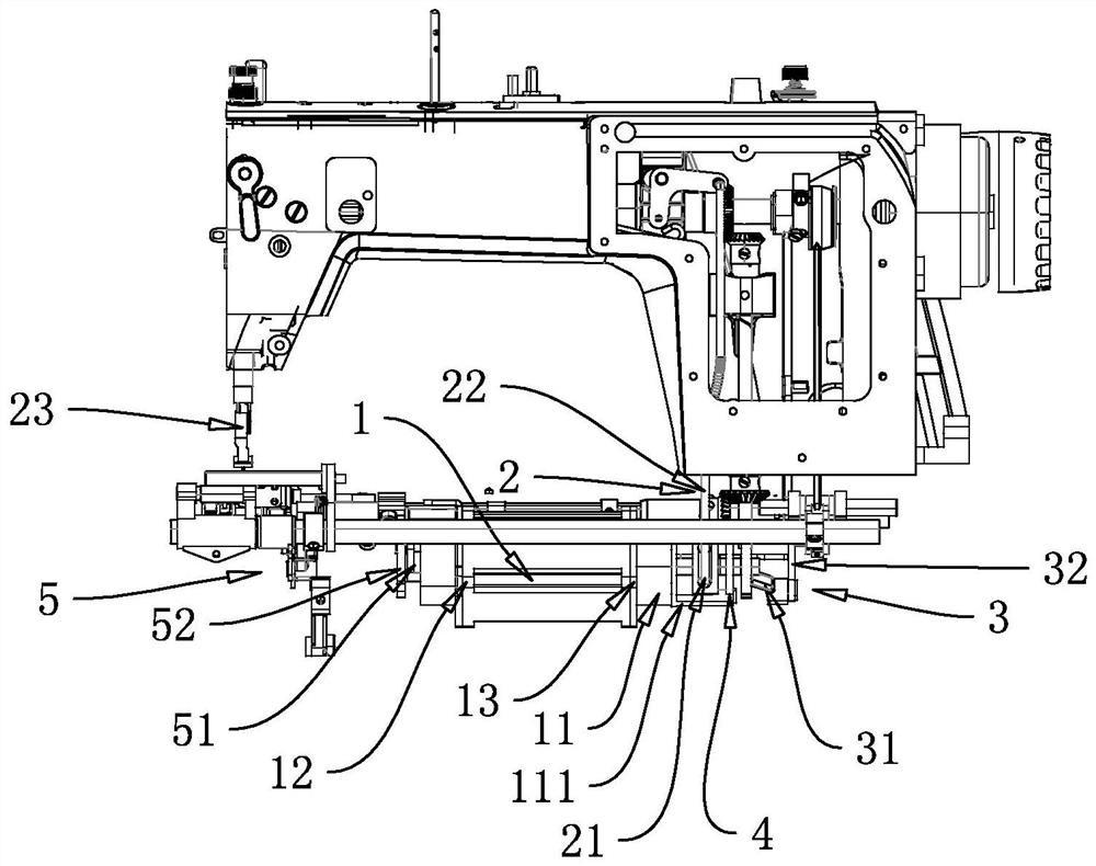
[0031] figure 1 figure 2 image 3 It is a structural diagram of a structure of multiple sewing actions controlled by one motor and a sewing machine of the present application. The structure of multiple sewing actions controlled by one motor specifically includes a motor 1, a presser foot lifting mechanism 2, a reverse stitching mechanism 3 and a thread trimming mechanism 5. The motor 1 includes an electromagnet 11 and / or a relay (the simultaneous solution of the electromagnet 11 of the present application uses a relay, and the effect is the same), an encoder 14, and the motor 1 has a front output shaft 12 and a rear output shaft 13. The rear output shaft 13 of 1 controls the presser foot lifting mechanism 2 and the reverse stitching mechanism 3, the rear output shaft 13 of the motor 1 passes through the electromagnet 11 and is fixed and fixed with the presser foot lifting cam 21, the transmission wheel 4 and the reverse stitching crank 31; The front output shaft 12 of the m...
Embodiment 2
[0041] This embodiment is basically the same as the first embodiment above, except that the presser foot lifter cam 21 of the presser foot lifter mechanism 2 is different.
[0042] exist Figure 10 Figure 11 Among them, the presser foot lifting cam 6 has a connecting rod groove 611, a rear shaft hole 614, a front low point 612 and a rear low point 613. The above presser foot lifting cam 6 is integrated with the electromagnet 11. Iron 11 pulls in and follows. The connecting rod slot 611 of the presser foot lifting cam 6 is open, and the presser foot lifting connecting rod 22 abutting against the connecting rod groove 611 can enter the presser foot lifting cam 6 laterally, and can leave the presser foot lifting cam 6 laterally. There is also a gap between the presser foot lifting cam 6 and the rear output shaft 13 to ensure that the presser foot cam 6 is displaced with the suction action of the electromagnet 11.
[0043] The above-mentioned presser foot lifting cam 6 has a c...
PUM
 Abstract
Description
Claims
Application Information