An automatic keel installation equipment for ceiling decoration
A technology for installing equipment and keels, which is applied in the field of automatic keel installation equipment for ceiling decoration, which can solve the problems of cumbersome manual operation procedures, low degree of automation, and low efficiency, and achieve the effects of improving aesthetics, liberating manpower, and avoiding danger
- Summary
- Abstract
- Description
- Claims
- Application Information
AI Technical Summary
Problems solved by technology
Method used
Image

Examples
Embodiment 1
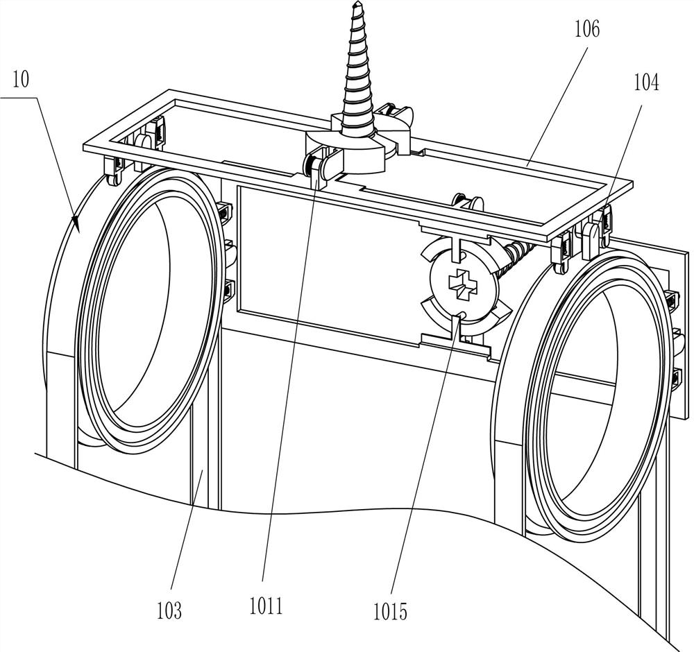
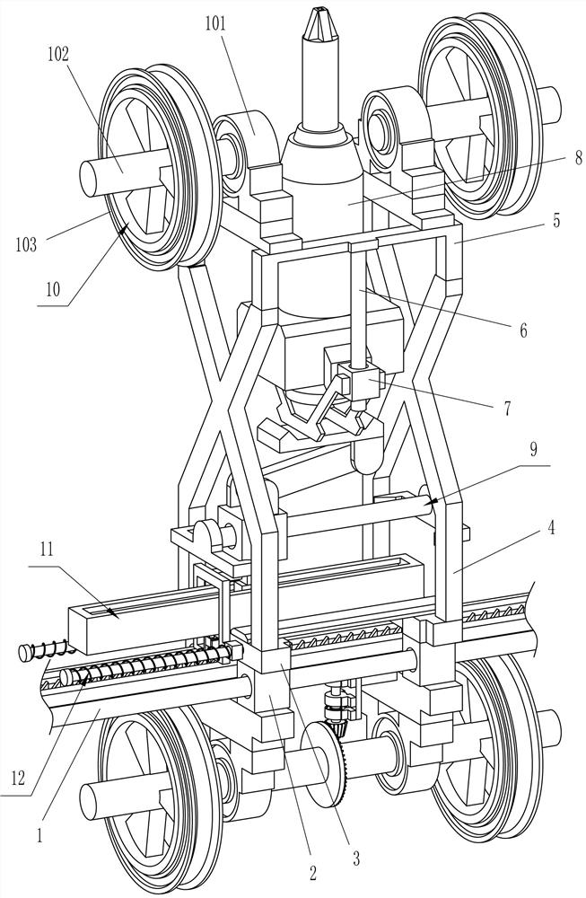
[0032] A kind of automatic keel installation equipment for ceiling decoration, such as Figure 1-4 As shown, it includes a first guide rail 1, a first guide sleeve 2, a mounting plate 3, a support frame 4, a fixed frame 5, a second guide rail 6, a second guide sleeve 7, an automatic screwdriver 8, a propulsion device 9, and a feeding device 10 And driving device 11, specifically:
[0033] Two sets of first guide rails 1 are slidingly connected with two first guide sleeves 2, and the upper sides of the front and rear first guide sleeves 2 on the left and right sides are connected with a mounting plate 3, and between the upper sides of the mounting plates 3 A support frame 4 is connected, a fixed frame 5 is connected between the upper side of the support frame 4, and a second guide rail 6 is connected to the front and rear sides of the lower side of the fixed frame 5, and the second guide rail 6 is slidably connected to a second guide sleeve 7 , an automatic screwdriver 8 is co...
Embodiment 2
[0036] On the basis of Example 1, such as Figure 4-10 As shown, the propulsion device 9 includes a third guide rail 91, a third guide sleeve 92, a contact block 93, a moving frame 94 and a connecting rod 95, specifically:
[0037] A third guide rail 91 is connected between the lower sides of the support frames 4, a third guide sleeve 92 is slidably connected to the third guide rail 91, and a contact block 93 is connected to the lower side of the third guide sleeve 92, and the contact block 93 is in contact with the driving device 11 , the lower side of the second guide sleeve 7 is connected with a moving frame 94 , and a connecting rod 95 is rotatably connected between the moving frame 94 and the third guide sleeve 92 .
[0038] When the driving device 11 contacts the contact block 93, the driving device 11 will drive the contact block 93 to move to the right, so that the contact block 93 will drive the third guide sleeve 92 to move to the right, and the third guide sleeve 92...
Embodiment 3
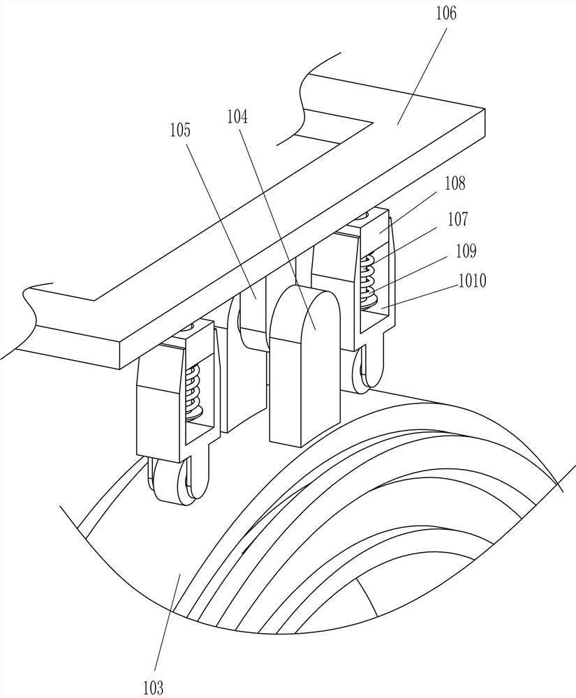
[0046] On the basis of Example 2, such as Figure 11-13 As shown, a traveling device 12 is also included, and the traveling device 12 includes a fifth guide rail 121, a fifth guide sleeve 122, a third elastic member 123, a displacement frame 124, a sixth guide sleeve 125, a sixth guide rail 126, a fourth elastic Part 127, cone block 128, connecting plate 129 and spine 1210, specifically:
[0047] The left side of the mounting plate 3 is provided with a traveling device 12, the traveling device 12 is in contact with the stroke block 113, the traveling device 12 is used to automatically drive the equipment to move, and the front and rear sides on the left side of the left mounting plate 3 are connected with the fifth guide rail 121 , the fifth guide rail 121 is slidingly connected with the fifth guide sleeve 122, the third elastic member 123 is connected between the fifth guide sleeve 122 and the fifth guide rail 121, and the displacement frame 124 is connected between the fifth...
PUM
 Abstract
Description
Claims
Application Information
 - R&D
- Intellectual Property
- Life Sciences
- Materials
- Tech Scout
- Unparalleled Data Quality
- Higher Quality Content
- 60% Fewer Hallucinations
Browse by: Latest US Patents, China's latest patents, Technical Efficacy Thesaurus, Application Domain, Technology Topic, Popular Technical Reports.
© 2025 PatSnap. All rights reserved.Legal|Privacy policy|Modern Slavery Act Transparency Statement|Sitemap|About US| Contact US: help@patsnap.com