Gas extraction device at upper corner of coal face of coal mine

A technology for coal mining face and gas extraction, which is applied in the directions of gas discharge, safety devices, mining equipment, etc., can solve the problems of reducing the work efficiency of gas extraction operations, and achieves avoiding the reduction of gas extraction efficiency, improving work efficiency, and improving Using the effect of the effect

Active Publication Date: 2020-09-29
杨东方
View PDF8 Cites 2 Cited by
  • Summary
  • Abstract
  • Description
  • Claims
  • Application Information

AI Technical Summary

Problems solved by technology

[0004] Existing upper corner gas extraction devices all use exhaust fans as the extraction power. Due to the long drainage pipelines, sometimes even up to thousands of meters, the suction of the exhaust fans decreases with the increase of the length, ser

Method used


Image

  • Gas extraction device at upper corner of coal face of coal mine
  • Gas extraction device at upper corner of coal face of coal mine
  • Gas extraction device at upper corner of coal face of coal mine

Examples


Embodiment Construction

[0025] The following will clearly and completely describe the technical solutions in the embodiments of the present invention with reference to the accompanying drawings in the embodiments of the present invention. Obviously, the described embodiments are only some, not all, embodiments of the present invention. Based on the embodiments of the present invention, all other embodiments obtained by persons of ordinary skill in the art without creative work, any modifications, equivalent replacements, improvements, etc., shall be included in the protection scope of the present invention Inside.

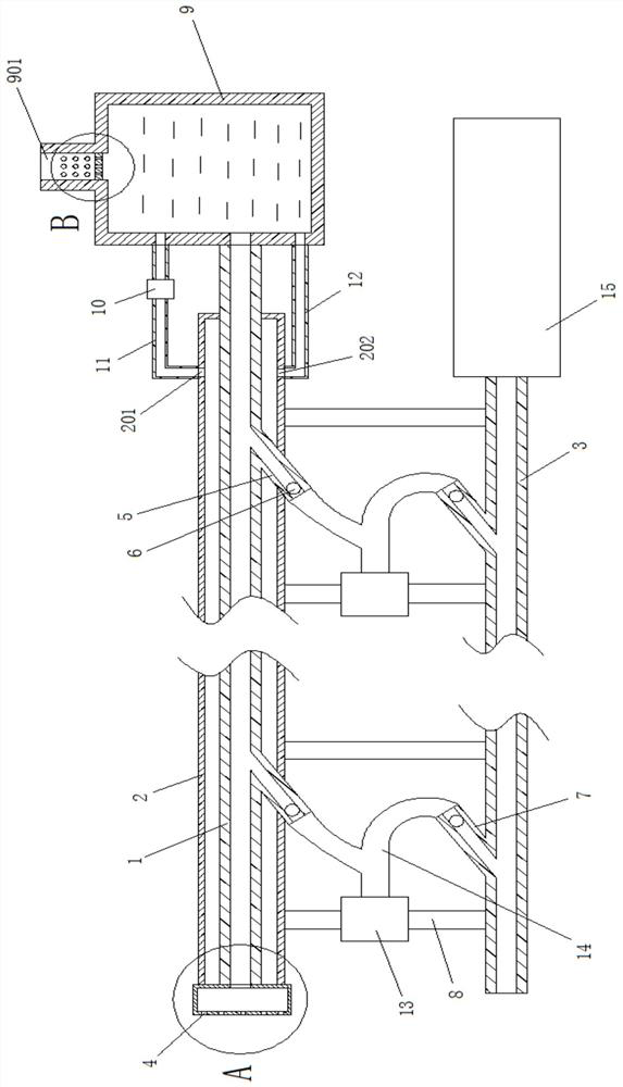
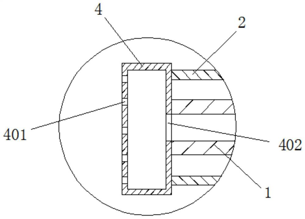
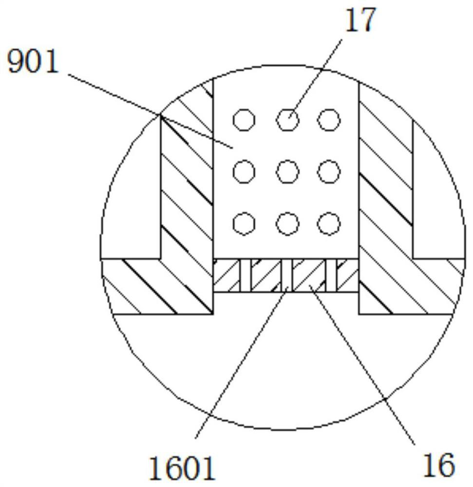
[0026] Such as Figure 1 to Figure 4 As shown, the gas extraction device at the upper corner of the coal mining working face in the coal mine in this embodiment includes an air extraction pipeline 1 and an air supply pipeline 3, and the air extraction pipeline 1 and the air supply pipeline 3 are fixedly connected by a fixed connection frame 8; One end of the gas pipeline 1 communicates w...


PUM


Abstract

The invention discloses a gas extraction device at an upper corner of a coal face of a coal mine. The gas extraction device comprises an extraction pipeline and a blowing pipeline, wherein the extraction pipeline and the blowing pipeline are fixedly connected through a fixed connecting rack; one end of the extraction pipeline communicates to a filter box body while the other end of the extractionpipeline communicates to a water storage tank body, and an exhaust pipeline is arranged at the top end of the water storage tank body; a plurality of first inclined connecting pipes are arranged on the side surface of the exhaust pipeline, and the included angle between the first inclined connecting pipe and the end, close to the filter box body, of the extraction pipeline is not greater than 75 degrees; one end of the blowing pipeline stretches into the coal face while the other end of the blowing pipeline communicates to an inertia gas tank, a plurality of second inclined connecting pipes are arranged on the side surface of the blowing pipeline, and the included angle between the second inclined connecting pipe and the end, lose to the inertia gas tank, of the blowing pipeline is not greater than 75 degrees; and a power fan is arranged on the fixed connecting rack, and an air outlet of the power fan communicates to the first inclined connecting pipes and the second inclined connecting pipes through an air outlet pipeline, separately.

Description


Claims


Application Information

Patent Timeline
Owner 杨东方
Why Eureka
Try Eureka