
Button valve

A key and valve body technology, used in sliding valves, valve details, multi-port valves, etc., can solve problems such as valve core blockage, and achieve the effect of expanding the scope of use

Inactive Publication Date: 2020-09-29
何仁熙
View PDF1 Cites 3 Cited by
  • Summary
  • Abstract
  • Description
  • Claims
  • Application Information

AI Technical Summary

Problems solved by technology

[0009] The purpose of the present invention is to overcome the deficiencies of the prior art, and provide a button valve, which solves the problem that the existing push-type valve core is prone to blockage, and at the same time increases the flow adjustment function

Method used


Image

  • Button valve
  • Button valve
  • Button valve

Examples


Embodiment

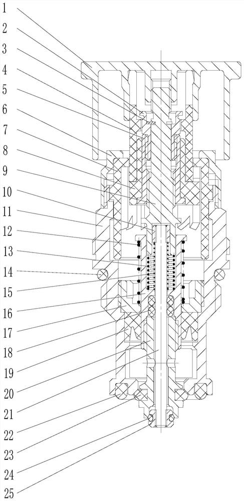
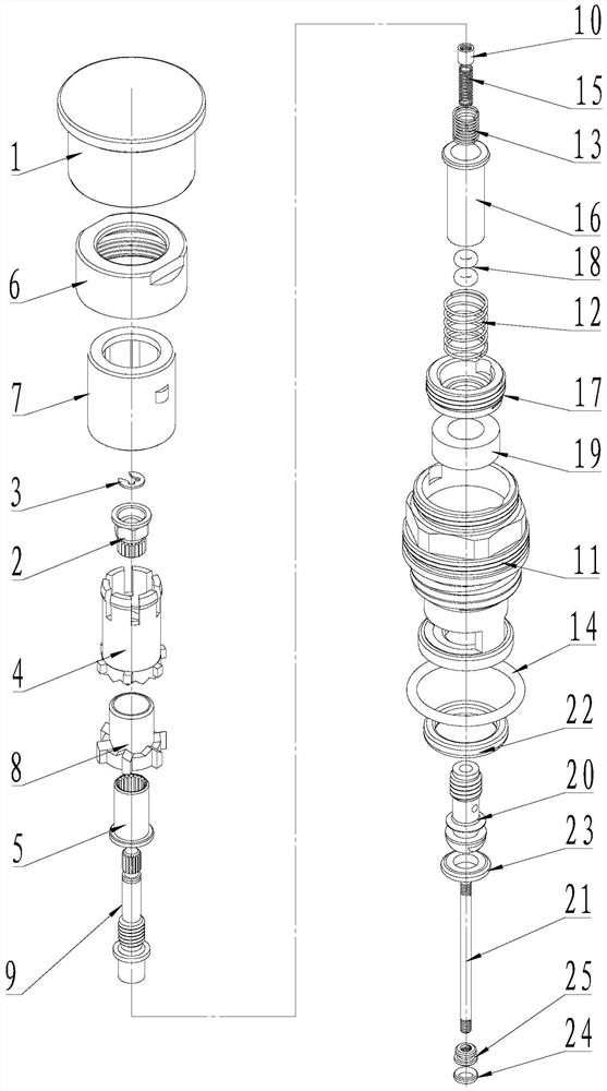
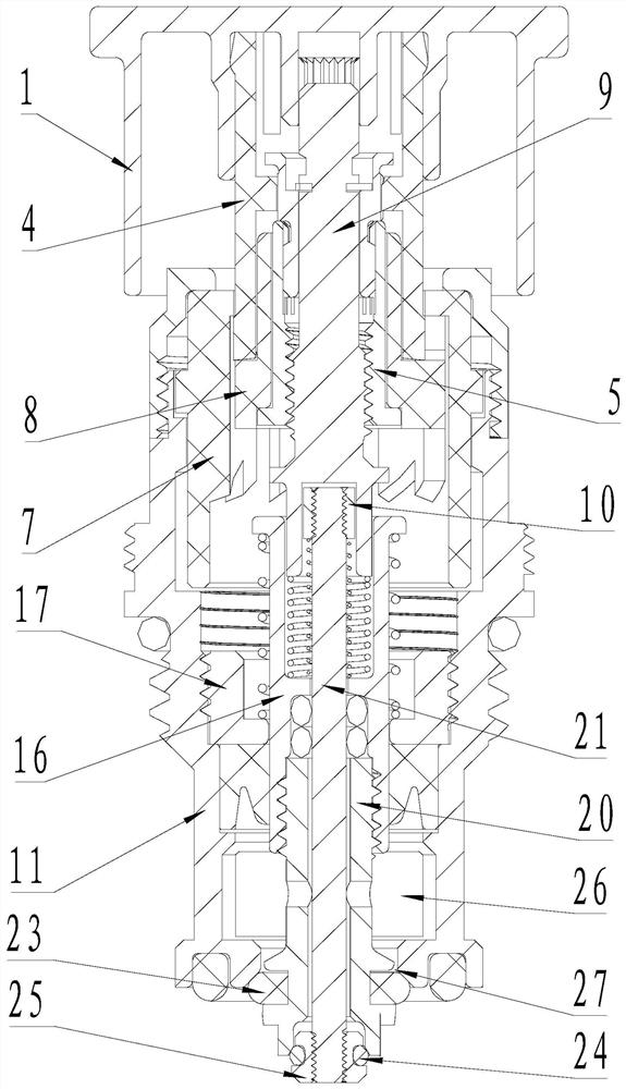
[0028] Example: as attached figure 1 , 2 As shown, this button valve includes a valve body 11, and the upper part of the valve body 11 is provided with a slide rail assembly and a locking sleeve 6 for locking the slide rail assembly. The slide rail assembly includes an outer sleeve 7, a middle sleeve 4 and The inner sleeve 8, the outer sleeve 7 is fixedly installed in the valve body 11 and locked with the locking sleeve 6, the middle sleeve 4 is slidably installed in the outer sleeve 7, the upper end of the middle sleeve 4 is connected with the handwheel 1 and fixed axially, on the handwheel Driven by 1, it reciprocates up and down along the axis of the outer jacket 7, and the inner sleeve 8 is set in the middle sleeve 4, and performs up-and-down reciprocating motion and intermittent rotary motion with the middle sleeve 4 and has two limit positions, far and near.

[0029] The top of the slide rail assembly is fixed with a hand wheel 1, and a telescopic adjustment mechanism i...


PUM


Abstract

The invention discloses a button valve, and relates to the field of bathroom products. The valve comprises a valve body. The upper of the valve body is provided with a slide rail component and a locking sleeve for locking the slide rail component. The top of the slide rail component is provided with a hand wheel. A telescopic adjustment mechanism is provided in the slide rail component. The lowerend of the telescopic adjusting mechanism is sleeved with a water opening component and a water closing component. The water opening component and the water closing component are hollow and used for placing a pressure reducing component. The pressure reducing component is arranged on the telescopic adjusting mechanism. A water outlet is arranged on the side wall of the lower part of the valve body. A water inlet is arranged on the bottom of the valve body. The water outlet is communicated with the water inlet, and the connection is controlled by the water opening component and the water closing component arranged on the lower part of the valve body. The opening and closing of a water passage is controlled by pressing down the hand wheel, and the working stroke of the water opening component and the water closing component is adjusted by rotating the hand wheel to change the opening size of the water passage, thereby realizing flow regulation. The valve solves the problem that existingpush-type valve cores are prone to be blocked, and at the same time the valve increases the flow adjustment function.

Description

technical field [0001] The invention relates to the technical field of bathroom products, in particular to a button valve. Background technique [0002] In the existing bathroom products, the valves used to realize the switch control of the waterway mainly adopt two kinds of sealing structures: the rotary switch valve and the push rod switch valve. Both of these structures belong to the rotary control valve, that is, the switch control of the valve needs to be driven by turning the handwheel or the handle. It is very easy to slip, so a non-slip structure needs to be designed; in addition, they all use the cooperation between ceramic sheets as the sealing method, and the ceramic sheets need to be coated with lubricating oil. The lubricating oil is easy to lose in the water environment. Once the lubricating oil is lost, its hand feeling will be better. In severe cases, the ceramic sheet will be worn and the sealing function will fail and water will leak. [0003] Chinese pat...

Claims


Application Information

Patent Timeline
Patent Type & Authority Applications(China)
IPC IPC(8): F16K31/60F16K31/44F16K3/26F16K3/314F16K27/04F16K11/07
CPCF16K3/262F16K3/314F16K11/0716F16K27/041F16K31/44F16K31/605
Inventor 何仁熙
Owner 何仁熙
Learn More