

Heat exchanger structure optimization method based on hot melt gas-liquid two-phase heat transfer structure
A technology of heat exchange structure and optimization method, which is applied in design optimization/simulation, instrument, calculation, etc., to achieve the effects of high coordination, improved material utilization, and novel production methods
Active Publication Date: 2022-06-03
TONGJI UNIV
View PDF1 Cites 0 Cited by
- Summary
- Abstract
- Description
- Claims
- Application Information
AI Technical Summary
Problems solved by technology
However, it cannot effectively meet the dual requirements of weight reduction and higher heat exchange efficiency.
Method used
View moreImage
Smart ImageViewing Examples

Examples
Embodiment 1
[0051] XL=x-bCos[(x / 2)^2]
[0052] YL=y-bCos[(y / 2)^2]
[0054] p1=ContourPlot3D[Cos[XL]Sin[YL]+
[0055]Con[YL]Sin[ZL]+Cos[ZL]Sin[XL]=0,
[0056] {x,-Pi,Pi},{y,-Pi,Pi},{z,-Pi,Pi}]
[0072] The iterative principle and structural principle of the heat exchanger structure optimization method of the present embodiment will be described in detail below.
[0075] The gas-liquid ratio parameter monomer unit cell model required to meet the target is adjusted by the parameters, and then through the fast iteration matrix
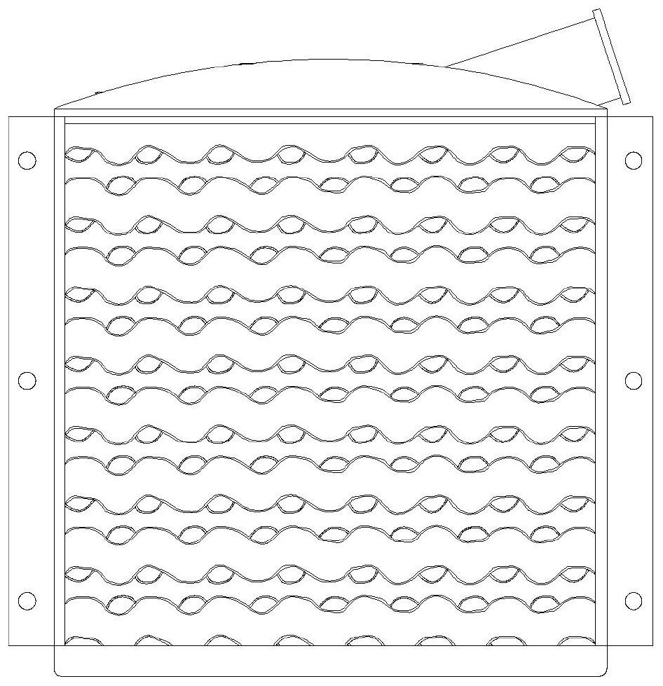
[0084] The wall thickness of the heat exchanger structure designed in this embodiment is 0.3mm, and the edge length of the unit body is 0.425*pi (mm), similar to
Login to View More PUM
 Abstract
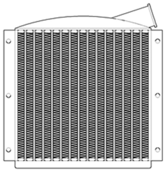
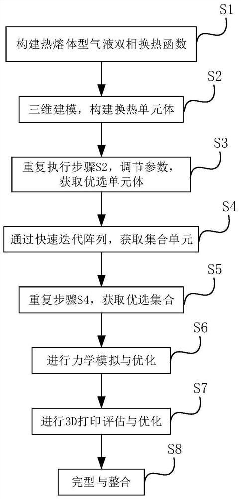
The invention relates to a heat exchanger structure optimization method based on a hot-melt type gas-liquid two-phase heat exchange structure, which includes the following steps: S1: according to the hot-melt type gas-liquid two-phase heat exchange structure and based on sine and cosine functions, construct a heat exchanger Melt-type gas-liquid two-phase heat transfer function; S2: Carry out three-dimensional modeling to construct the heat transfer unit. S3: Repeat step S2, adjust parameters, and obtain the optimal unit body that meets the preset gas-liquid volume ratio condition; S4: Obtain the aggregate unit composed of the optimal unit body through rapid iterative array; S5: Repeat step S4, Obtain the optimized set with the best surface area and quality; S6: Perform stress optimization; S7: Perform 3D printing optimization; S8: Integrate the optimized set to obtain the final heat exchanger structure. Compared with the prior art, the present invention adopts a hot-melt type gas-liquid two-phase heat exchange structure, which breaks through the selection of traditional design structure modes, and achieves double breakthroughs in heat transfer efficiency and weight.
Description
Heat exchanger structure optimization method based on hot melt gas-liquid two-phase heat exchange structure technical field The present invention relates to the field of heat exchanger structure, especially relate to a kind of based on hot melt type gas-liquid two-phase heat exchange structure. Heat exchanger structure optimization method. Background technique The traditional heat exchanger structural design relies on the manufacturing process of subtractive manufacturing, and it is difficult to make relatively complex shapes, one To a certain extent, the further improvement of the relevant heat exchange efficiency is limited. Although the related design relies on reducing the cell spacing and increasing the ripple The plate method effectively increases the relevant contact area, but still cannot get rid of the fact that the heat transfer area is smaller than the material area. none The method achieves the full utilization of the material area, resulting in a certa...
Claims
Login to View More Application Information
Patent Timeline
 Patent Type & AuthorityPatents(China)
IPC IPC(8): G06F30/20G06F119/14G06F113/08G06F119/08
CPCG06F30/20G06F2119/14G06F2119/08G06F2113/08
Inventor严鹏飞尹泽诚严彪
OwnerTONGJI UNIV