Rotating motor and rotor shaft
A technology for rotating electrical machines and rotor shafts, applied in the field of rotating electrical machines and their rotor shafts, can solve the problems of increasing internal fan pressure and capacity, increasing mechanical losses of rotating electrical machines, etc., and achieve the effect of effective cooling
- Summary
- Abstract
- Description
- Claims
- Application Information
AI Technical Summary
Problems solved by technology
Method used
Image

Examples
no. 1 approach
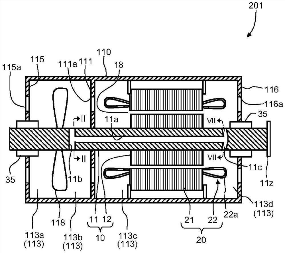
[0027] figure 1 It is a vertical cross-sectional view of the rotating electric machine according to the first embodiment. The rotary electric machine 201 has a rotor 10 , a stator 20 , two bearings 35 , a frame 110 , and two bearing brackets 115 , 116 .
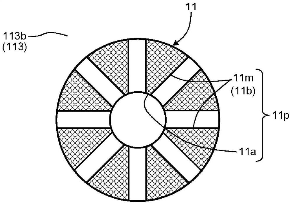
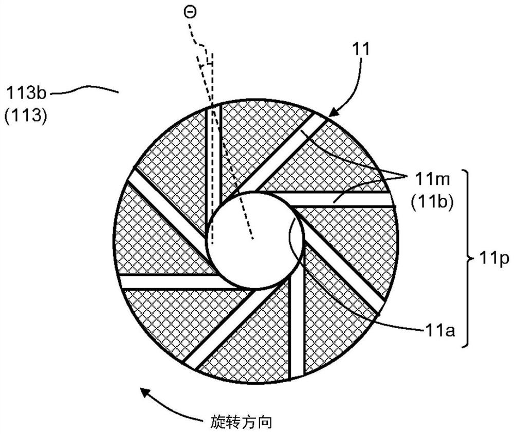
[0028] The rotor 10 has a rotor shaft 11 extending in the direction of the rotation axis, and a rotor core 12 attached to the radially outer side of the rotor shaft 11 . The rotor shaft 11 is rotatably supported by bearings 35 on both sides in the axial direction across the rotor core 12 .
[0029] At one end of the rotor shaft 11, a coupling portion 11z for coupling with a coupling partner is provided. Hereinafter, in the rotary electric machine 201 , the direction of the coupling portion 11 z is referred to as a coupling side, and the opposite direction is referred to as an opposite coupling side. A fan 118 is attached to the rotor shaft 11 between the rotor core 12 and the bearing 35 on the opposite side.
[0030] The ...
no. 2 approach
[0058] Figure 9 It is a vertical cross-sectional view of the rotating electric machine according to the second embodiment. This second embodiment is a modification of the first embodiment. The rotating electric machine 202 according to the second embodiment does not have the fan 118 in the rotating electric machine 201 according to the first embodiment. In the rotating electrical machine 202 according to the second embodiment, the two bearings 35 are arranged in the frame 120 . Therefore, the coupling-side bearing bracket (first bearing bracket) 121 and the coupling-side bearing bracket (second bearing bracket) 122 are mounted on the stator 20 so as to partition the inside of the frame 120 in the axial direction. frame 120. Inlet ventilation holes 121 a are formed in the bearing bracket (first bearing bracket) 121 on the side opposite to the coupling. In addition, an outlet ventilation hole 122 a is formed in the coupling-side bearing bracket (second bearing bracket) 122 ...
no. 3 approach
[0067] Figure 10 It is a vertical cross-sectional view of the rotating electric machine according to the third embodiment. This third embodiment is a modification of the first embodiment. In the rotating electrical machine 203 according to the third embodiment, at least one in-frame flow path 131 is formed in the frame 130 . The in-frame channel 131 has a cross-section in a region sandwiched between the inner surface and the outer surface of the frame 130 and extends in the axial direction. The end portion of the in-frame flow path 131 on the coupling-side bearing bracket (second bearing bracket) 136 side communicates with the inner space 114 a of the frame 130 via a flow path inlet 131 a. In addition, the end portion of the in-frame flow path 131 on the opposite side to the bearing bracket (first bearing bracket) 135 communicates with the inner space 114b of the frame 130 via the flow path inlet 131b.
[0068]No opening communicating with the outside is formed in the coup...
PUM
 Abstract
Description
Claims
Application Information
 - R&D
- Intellectual Property
- Life Sciences
- Materials
- Tech Scout
- Unparalleled Data Quality
- Higher Quality Content
- 60% Fewer Hallucinations
Browse by: Latest US Patents, China's latest patents, Technical Efficacy Thesaurus, Application Domain, Technology Topic, Popular Technical Reports.
© 2025 PatSnap. All rights reserved.Legal|Privacy policy|Modern Slavery Act Transparency Statement|Sitemap|About US| Contact US: help@patsnap.com