Portable high-precision grinding equipment for civil engineering
A portable, civil engineering technology, applied in metal processing equipment, grinding/polishing equipment, portable grinding bed, etc., can solve the problems of affecting the grinding effect, construction effect, incomplete functions, etc., and achieve the convenience of movement and transportation Effect
- Summary
- Abstract
- Description
- Claims
- Application Information
AI Technical Summary
Problems solved by technology
Method used
Image
Examples
Embodiment 1
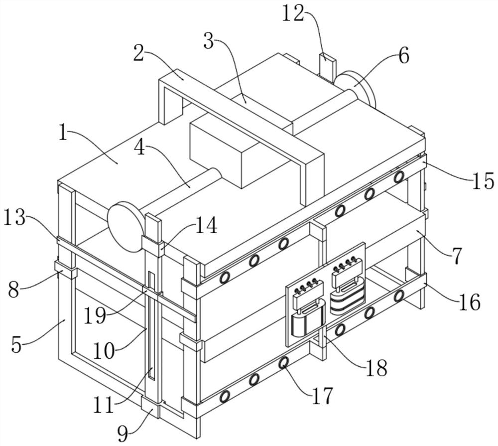
[0034] see figure 1, a portable high-precision grinding equipment for civil engineering, including an installation top plate 1, the center of the installation top plate 1 is fixedly connected with a transmission box 3, the outside of the transmission box 3 is provided with a handle bar 2, and the two ends of the handle bar 2 are fixedly connected to the installation top plate 1 upper wall surface; brackets 5 are fixedly connected to both sides of the installation top plate 1, and a clamping box 7 is arranged between the brackets 5, and sleeve blocks A8 are fixedly connected to both sides of the clamping box 7, and the sleeve block A8 is slidably connected to the bracket 5; The center of the upper surface of the installation top plate 1 is fixedly connected with a sleeve 4, the sleeves 4 are arranged on both sides of the transmission box 3 respectively, the end of the sleeve 4 is fixedly connected with a gear plate 6, and the gear plate 6 is fixedly connected to the edge of the ...
Embodiment 2
[0037] see Figure 1-3 , based on Example 1, the difference is that:
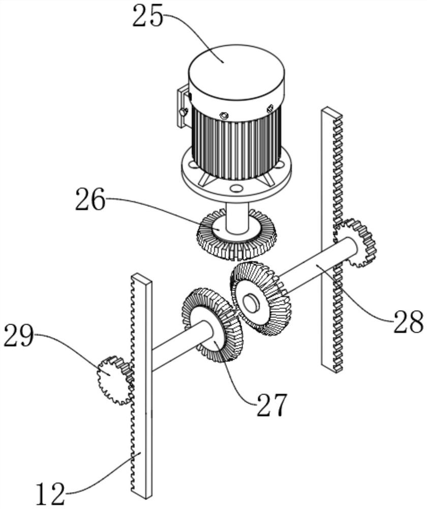
[0038] The inside of the transmission box 3 is provided with a motor A25, and the upper end of the motor A25 is fixedly connected to the inner top surface of the transmission box 3; the lower part of the motor A25 is fixedly connected to the driving wheel 26 through the output shaft, and the two sides of the driving wheel 26 are meshed with the driven wheel 27 respectively. 26 and driven wheel 27 are conical wheels.
[0039] The outer side of the driven wheel 27 is fixedly connected with the driving wheel 29 through the connecting shaft 28, and one side of the two driving wheels 29 is meshed with the lifting rod A10 and the lifting rod B12 respectively, and the central inner sides of the lifting rod A10 and the lifting rod B12 are respectively connected to the clamping box 7. The side is fixedly connected; the lifting rod A10 and the lifting rod B12 are respectively slidably connected to the inside of the ...
Embodiment 3
[0043] see Figure 1-2 , based on Embodiment 1 and 2, the difference is: .
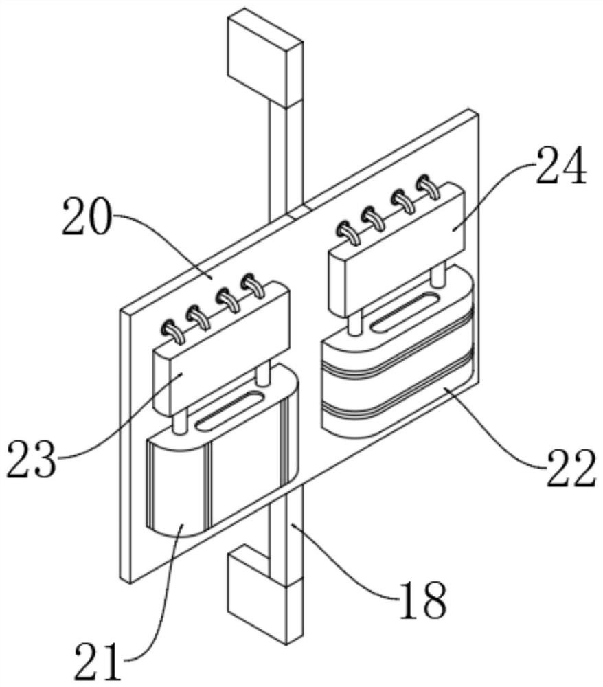
[0044] A crossbeam A15 and a crossbeam B16 are also arranged between the brackets 5 on both sides, and the crossbeam A15 and the crossbeam B16 are fixedly connected to the upper and lower sides of the clamping box 7 respectively; a connecting frame A18 is fixedly connected between the crossbeam A15 and the crossbeam B16, and the central part of the connecting frame A18 The outer side is fixedly connected with an installation side plate 20;
[0045] Installation side plate 20 external two ends are respectively fixedly connected with water storage tank 21 and dust collection box 22, and water storage tank 21 top is connected with water pump 23, and dust collection box 22 top is connected with dust collector 24; Water pump 23 and dust collection machine 24 are all fixed Connected to the installation side plate 20, the output end of the water pump 23 is fixedly connected with a number of water spray pipe...
PUM
 Abstract
Description
Claims
Application Information
 - R&D
- Intellectual Property
- Life Sciences
- Materials
- Tech Scout
- Unparalleled Data Quality
- Higher Quality Content
- 60% Fewer Hallucinations
Browse by: Latest US Patents, China's latest patents, Technical Efficacy Thesaurus, Application Domain, Technology Topic, Popular Technical Reports.
© 2025 PatSnap. All rights reserved.Legal|Privacy policy|Modern Slavery Act Transparency Statement|Sitemap|About US| Contact US: help@patsnap.com


