Eureka AIR delivers breakthrough ideas for toughest innovation challenges, trusted by R&D personnel around the world.

Protective fence for highway and mounting method thereof

A technology for guardrails and highways, applied in road safety devices, roads, roads, etc., can solve the problems of limited deformation ability and energy absorption ability, the angle of guardrail and guardrail cannot be freely adjusted, and the safety impact of cars and drivers. Achieve the effect of avoiding secondary injury, protecting the safety of people in the car, and reducing the impact force in the car

Pending Publication Date: 2020-10-02
河南省吉安路桥工程有限公司
View PDF5 Cites 11 Cited by
  • Summary
  • Abstract
  • Description
  • Claims
  • Application Information

AI Technical Summary

Problems solved by technology

[0003] 1. In the prior art, the guardrails on both sides of the expressway are mainly composed of columns and guardrails on the upper part. The guardrails are made of steel plates. Both the columns and the guardrails are made of rigid materials. When a car hits the guardrails, only It can rely on the deformation and damage of the guardrail to absorb energy. The deformation ability and the ability to absorb energy are limited, so that the guardrail cannot buffer the car, but can only bear the impact of the car, which affects the safety of the car and the driver to a certain extent.
[0004] 2. In the prior art, the installation between the guardrail and the guardrail is mostly connected by bolts and nuts, and the angle between the guardrail and the guardrail after the connection is completed is easy to adjust, resulting in the angle between the guardrail and the guardrail. The actual demand can be adjusted freely, so that the scope of application of the guardrail is affected to a certain extent

Method used


Image

  • Protective fence for highway and mounting method thereof
  • Protective fence for highway and mounting method thereof
  • Protective fence for highway and mounting method thereof

Examples


Embodiment Construction

[0027] The following will clearly and completely describe the technical solutions in the embodiments of the present invention with reference to the accompanying drawings in the embodiments of the present invention. Obviously, the described embodiments are only some, not all, embodiments of the present invention. Based on the embodiments of the present invention, all other embodiments obtained by persons of ordinary skill in the art without making creative efforts belong to the protection scope of the present invention.

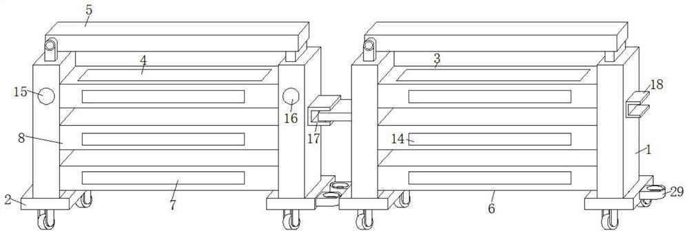
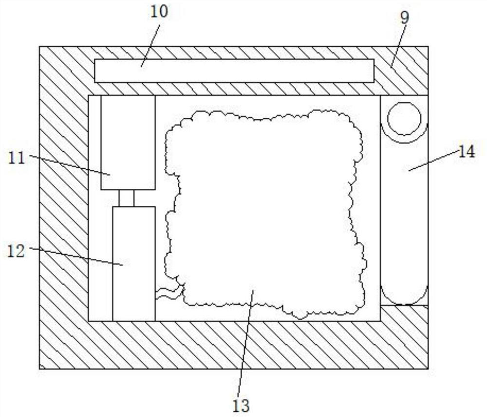
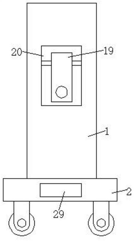
[0028] see Figure 1-4 , a guardrail for highways, comprising two brackets 1 and a connecting mechanism 17, the bottom ends of the two brackets 1 are fixedly equipped with sliding seats 2, and an upper beam 3 is fixedly installed between the two brackets 1, The lower beam 6 and the warning buffer mechanism 8, the top of the upper beam 3 is fixedly equipped with a solar panel 4, the front end of the left side bracket 1 is fixedly equipped with a distance sensor...


PUM


Abstract

The invention discloses a protective fence for a highway and a mounting method thereof, whichrelate to the technical field of protective fences. The protective fence comprises two supports and a connecting mechanism, sliding seats are fixedly installed at the bottom ends of the two supports, an upper cross beam, a lower cross beam and a warning buffer mechanism are fixedly installed between the two supports, a solar cell panel is fixedly installed at the top of the upper cross beam, a distance sensor is fixedly installed at the front end of the left support, and an alarm is fixedly installed at the front end of the right support. The distance between a vehicle and the protective fencecan be monitored in real time through the distance sensor, and when the warning range is reached, a drivercan be reminded to keep a safe distance. And when the possible collision range is reached, the air bag is controlled to pop up, so that the impact force onthe vehicle is buffered, the deformation quantity of the collision vehicle can be effectively reduced, the recoil force caused by collision is minimized, secondary damage caused by the fact that the vehicle rushes out of the fenceis avoided, thecollision force in the vehicle during a traffic accident is reduced, and the safety of personnel in the vehicle is protected.

Description

technical field [0001] The invention relates to the technical field of guardrails, in particular to a guardrail for expressways and an installation method thereof. Background technique [0002] The expressway guardrail is the most important transportation infrastructure. The expressway in our country was developed in the 1980s, and it plays an important role in the development of the national economy and society. It is an important maintenance and safety guarantee facility for highways. Highway guardrails are also known as: highway guardrail nets, highway guardrail panels, highway guardrails, highway isolation fences, and highway net fences. [0003] 1. In the prior art, the guardrails on both sides of the expressway are mainly composed of columns and guardrails on the upper part. The guardrails are made of steel plates. Both the columns and the guardrails are rigid materials. When a car hits the guardrails, only It can rely on the deformation of the guardrail to damage the...

Claims


Application Information

Patent Timeline
Patent Type & Authority Applications(China)
IPC IPC(8): E01F15/10E01F9/669E01F9/619E01F9/608
CPCE01F15/006E01F9/608E01F9/619E01F9/669
Inventor 赵永旗杨朝旭刘成永白涛张昆山于会江孟秀娟李晓燕赵永凯
Owner 河南省吉安路桥工程有限公司
Why Eureka
Eureka Blog
Learn More