A multifunctional hydraulic safety device for oil pipe

A safety device and multi-functional technology, applied in the direction of wellbore/well valve device, drill pipe, casing, etc., can solve the problems of poor safety performance, long time, cumbersome operation, etc., and achieve the effect of reasonable structural design

Active Publication Date: 2022-01-18
HELI TECH ENERGY CO LTD
View PDF7 Cites 0 Cited by
  • Summary
  • Abstract
  • Description
  • Claims
  • Application Information

AI Technical Summary

Problems solved by technology

[0002] Hydraulic safety joints are widely used in the layered production of oil wells in the casing and gas and water jams. The implementation of this set of technology can shorten the workover time of oil wells and restore production to some shut-down oil wells caused by serious gas channeling. , and realize the layered production and selective production of oil wells completed with small-diameter casings. It is a downhole tool that throws the buried part of the completion string into the well. The hand-dropping device can separate the upper and lower pipe strings, so as to lift out the upper pipe string. However, in the prior art, the design similar to this tool requires the ball to be pressed to realize the release function. Moreover, the current related tools, in order to prevent the underground high-pressure gas And the sudden pressure rise of high-pressure oil is greater than the pressure of drilling fluid, which will cause danger to flow upward in reverse. The one-way valve mechanism is adopted. The one-way valve mechanism is the structure of torsion spring and valve cover. The safety performance is poor, and some have bypass The valve mechanism, when the drilling fluid circulates, the lower drill bit is blocked, the pipe is overpressured, the pump is stopped and the ball is thrown, the pump is turned on to suppress the shear pin, and the bypass is opened. The operation is cumbersome and takes a long time

Method used


Image

  • A multifunctional hydraulic safety device for oil pipe
  • A multifunctional hydraulic safety device for oil pipe
  • A multifunctional hydraulic safety device for oil pipe

Examples


Embodiment Construction

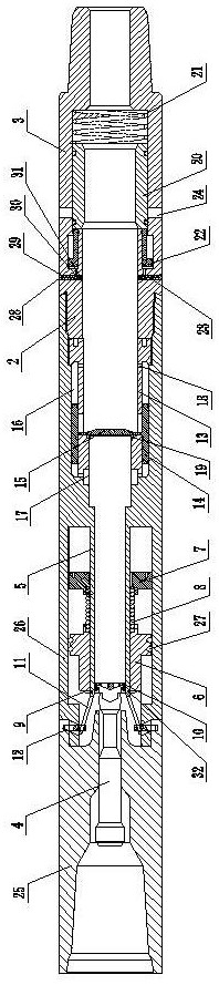
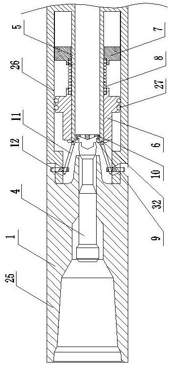
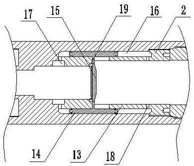
[0015] A oil pipe multifunctional hydraulic safety device of the present invention is composed of a discarding pipe section 1, a pressure equalizing pipe section 2 and a pressure relief pipe section 3. The discarding pipe section 1 is composed of an upper pipe section 25 and a lower pipe section 26 connected internally and externally. The upper pipe section 25 The port is connected with the lower part of the last section of the oil pipe. A hydraulic impact hammer 4 with clearance fit is provided on the axis of the upper inner cavity of the upper pipe section 25, and an inner cylinder 5, the inner cylinder 5 and the lower pipe section are provided on the axis of the lower section 26. The sliding sleeve 6 is fit in the gap between the annular gaps between 26, and a thrust spring 8 is embedded between the lower end of the sliding sleeve 6 and the limit seat 7, and a lock hook 9 and a lock catch 10 are connected to the upper end of the sliding sleeve 6. Buckle the relative lock hoo...


PUM


Abstract

A oil pipe multifunctional hydraulic safety device of the present invention belongs to the technical field of petroleum operation equipment and is composed of a discarding pipe section, a pressure equalizing pipe section and a pressure relief pipe section. A pressure equalizing inner cylinder is provided; the pressure relief pipe section is connected with the upper end of the pressure equalization pipe section, and a sliding sleeve is fitted in the clearance of the pressure relief pipe section. The oil pipe multifunctional hydraulic safety device of the present invention cancels the pressing link, and its mechanical mechanism can realize the function of releasing the hand, and uses the principle of pressure difference, uses the structure of the hydraulic valve cover, and adopts the safety valve mechanism at the same time, and the overpressure is automatically opened The bypass valve is automatically closed by misoperation, and its structural design is reasonable, which effectively makes up for the deficiencies of the prior art and meets the needs of actual conditions.

Description

technical field [0001] The invention belongs to the technical field of petroleum operation equipment, in particular to a multifunctional hydraulic safety device for oil pipes. Background technique [0002] Hydraulic safety joints are widely used in the layered production of oil wells in the casing and gas and water jams. The implementation of this set of technology can shorten the workover time of oil wells and restore production to some shut-down oil wells caused by serious gas channeling. , and realize the layered production and selective production of oil wells completed with small-diameter casings. It is a downhole tool that throws the buried part of the completion string into the well. The hand-dropping device can separate the upper and lower pipe strings, so as to lift out the upper pipe string. However, in the prior art, the design similar to this tool requires the ball to be pressed to realize the release function. Moreover, the current related tools, in order to pre...

Claims


Application Information

Patent Timeline
Patent Type & Authority Patents(China)
IPC IPC(8): E21B17/08E21B34/08
CPCE21B17/08E21B34/08
Inventor 单军锋侯立东梁杰冯炜
Owner HELI TECH ENERGY CO LTD
Why Eureka
Try Eureka