
Ore pulp pipeline sampler convenient to seal

A sampler and pipeline technology, applied in the field of slurry pipeline sampler, can solve the problems of affecting production efficiency, poor sealing effect, leaking sampler, etc., and achieve the effect of improving sampling efficiency, service life and sealing effect

Inactive Publication Date: 2020-10-02
范文
View PDF0 Cites 0 Cited by
  • Summary
  • Abstract
  • Description
  • Claims
  • Application Information

AI Technical Summary

Problems solved by technology

[0003] However, the traditional slurry pipeline sampler still has the following problems in actual use: First, by inserting the sampling tube into the slurry for sampling, the sampling tube will inevitably be impacted by the slurry during sampling, which will not only affect the flow rate of the slurry In addition, the sampling tube is easily damaged under the long-term impact of the slurry, and the sampling head and the base adopt a cylindrical structure, which has a poor sealing effect and is prone to slurry leakage. , it is necessary to stop the entire slurry production line and disassemble the entire pipeline sampler for maintenance, which seriously affects the production efficiency; secondly, the traditional slurry pipeline sampler can only sample a certain position of the slurry section when sampling. Instead of sampling the entire cross-section of the pulp, this sampling method has poor representativeness of the sampling data and low sampling efficiency

Method used


Image

  • Ore pulp pipeline sampler convenient to seal
  • Ore pulp pipeline sampler convenient to seal
  • Ore pulp pipeline sampler convenient to seal

Examples


Embodiment Construction

[0022] The following will clearly and completely describe the technical solutions in the embodiments of the present invention with reference to the accompanying drawings in the embodiments of the present invention. Obviously, the described embodiments are only some of the embodiments of the present invention, not all of them. Based on the embodiments of the present invention, all other embodiments obtained by persons of ordinary skill in the art without making creative efforts belong to the protection scope of the present invention.

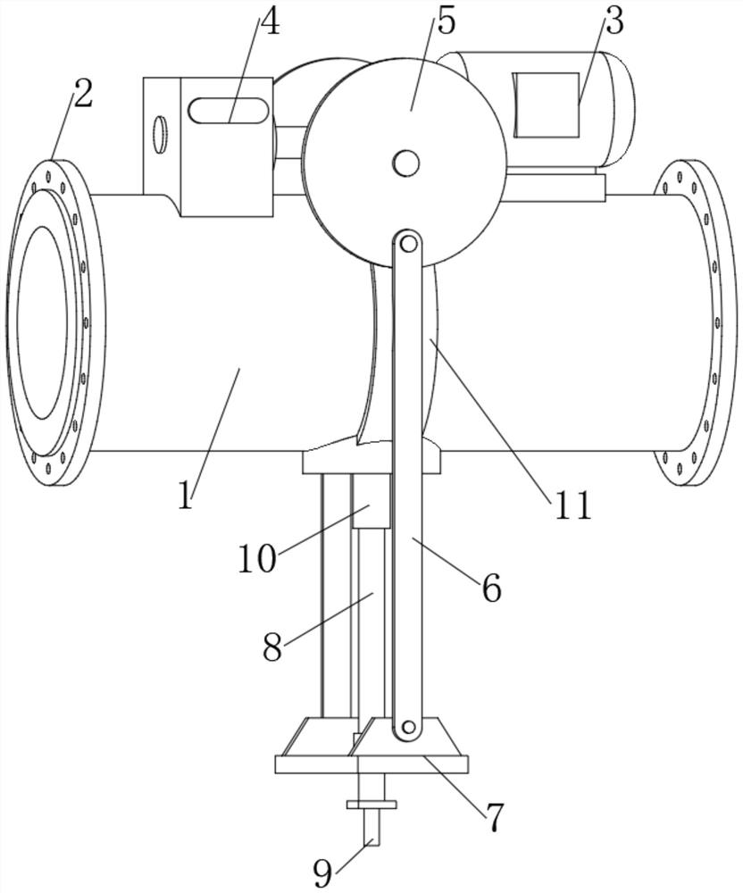
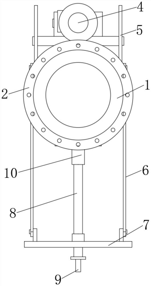
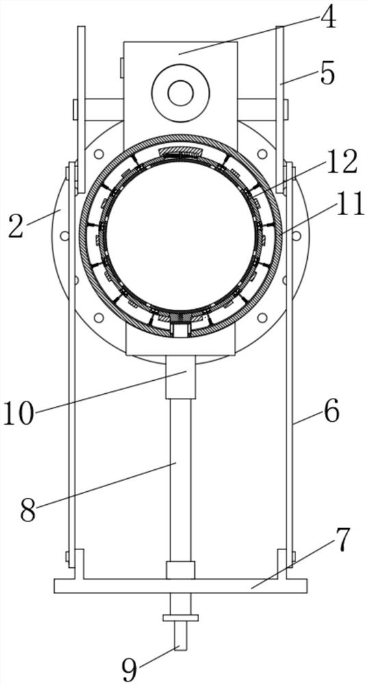
[0023] see Figure 1-8 , a slurry pipeline sampler that is easy to seal, including a pipe body 1, flanges 2 are connected to both sides of the pipe body 1, a rotating motor 3 is fixedly connected to one side of the upper part of the pipe body 1, and the output of the rotating motor 3 The shaft end is fixedly connected with a reducer 4, and one end of the reducer 4 is meshed with a transmission wheel 5, and the front side of the transmission wheel...


PUM


Abstract

The invention relates to the technical field of ore pulp sampling equipment, and discloses a convenient-to-seal ore pulp pipeline sampler. The sampler comprises a pipe body, and flange plates are connected to the two sides of the pipe body through pipelines; a rotating motor is fixedly connected to one side of the upper portion of the pipe body, and a speed reducer is fixedly connected to the output shaft end of the rotating motor. Through the arrangement of a sampling pipe and a sliding ring, the sampling pipe can be used for sampling without being inserted into ore pulp; the sampling pipe isnot impacted by ore pulp, so the service life of the sampling pipe is prolonged; moreover, after the sampling is finished, the through holes and the circulating holes are sealed in a staggered manner, and ore pulp is prevented from continuously flowing into the sampling pipe, so the sealing effect is improved; when the sampler breaks down, only the whole sampling pipe needs to be detached, at themoment, the circulation hole and the through hole of the sliding ring are still in a staggered and sealed state under the action of the limiting block and the reset spring, the whole ore pulp production line does not need to be stopped, the whole pipeline sampler does not need to be taken down to be maintained, and the production efficiency is improved.

Description

technical field [0001] The invention relates to the technical field of pulp sampling equipment, in particular to a pulp pipeline sampler which is convenient for sealing. Background technique [0002] In the process of mineral processing production, it is often necessary to take out ore samples from the process pipeline for chemical analysis or instrumental analysis, such as providing ore samples for particle size analyzers and X-ray fluorescence analyzers, and mineral processing plants generally use slurry pipeline samplers for sampling. Its working principle It is as follows: a sampling tube is installed on the base, a sampling head is arranged in the sampling tube, and the driving device drives the sampling rod to move up and down in the pulp tube, so that the sampling hole on the sampling head cooperates with the base so that the sampling hole and the pulp tube are in a state of being in contact with each other. There are two states of blockage, sampling is performed when...

Claims


Application Information

Patent Timeline
IPC IPC(8): G01N1/20G01N1/16
CPCG01N1/16G01N1/2042
Inventor 范文
Owner 范文
Learn More