
High-precision injection mold with automatic ejection structure and high stability

A technology with structural stability and automatic ejection, which can be used in cleaning methods, cleaning methods and utensils, chemical instruments and methods using gas flow, etc. To achieve the effect of reducing manual demoulding time, improving work efficiency and increasing smoothness

Inactive Publication Date: 2020-10-09
赵言良
View PDF0 Cites 2 Cited by
  • Summary
  • Abstract
  • Description
  • Claims
  • Application Information

AI Technical Summary

Problems solved by technology

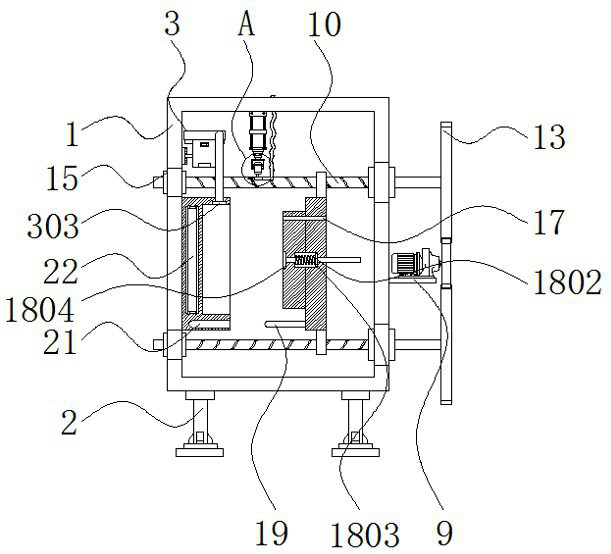
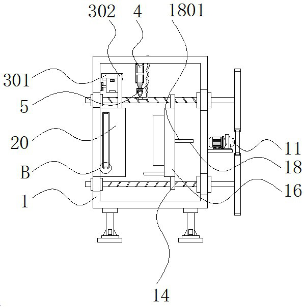
[0004] The purpose of the present invention is to provide a high-precision injection mold with automatic ejection structure and strong stability, so as to solve the problem that the existing high-precision injection mold proposed in the above-mentioned background technology requires manual or external equipment to reduce the mold removal during use. Improve the working efficiency of the equipment. The existing high-precision injection molds will have some slight deviations after each docking. When the molds are used for a long time, the deviation will increase and reduce the accuracy of the equipment. The existing high-precision injection molds need to be preheated manually. It is a waste of time, and it is not convenient to control the temperature within a certain range. The surface of the existing high-precision injection mold is prone to dust and other sundries, which is likely to have a certain impact on the product. It is easy to discharge the problem that air bubbles are easily generated on the surface of the product and affect the appearance of the product

Method used


Image

  • High-precision injection mold with automatic ejection structure and high stability
  • High-precision injection mold with automatic ejection structure and high stability
  • High-precision injection mold with automatic ejection structure and high stability

Examples


Embodiment Construction

[0028] The following will clearly and completely describe the technical solutions in the embodiments of the present invention with reference to the accompanying drawings in the embodiments of the present invention. Obviously, the described embodiments are only some, not all, embodiments of the present invention.

[0029] In the description of the present invention, unless otherwise stated, the meaning of "plurality" is two or more; the terms "upper", "lower", "left", "right", "inner", "outer" , "front end", "rear end", "head", "tail", etc. indicate the orientation or positional relationship based on the orientation or positional relationship shown in the drawings, and are only for the convenience of describing the present invention and simplifying the description, rather than Nothing indicating or implying that a referenced device or element must have a particular orientation, be constructed, and operate in a particular orientation should therefore not be construed as limiting ...


PUM


Abstract

The invention relates to a high-precision injection mold with an automatic ejection structure and high stability. The high-precision injection mold with the automatic ejection structure and the high stability comprises a fixed support and a lower mold body. Supporting legs are fixed to the lower portion of the fixed support, and an air exhaust mechanism, a multi-stage air cylinder and a high-pressure air conveying pipe are sequentially arranged on the inner upper portion of the fixed support from left to right. A mounting block, a second motor and a threaded rod are mounted on the side face ofthe fixed support from bottom to top, and a second gear, a wheel shaft and a threaded block are mounted on the outer surface of the threaded rod from right to left. The high-precision injection moldwith the automatic ejection structure and the high stability has the beneficial effects that the equipment is convenient to demold and has a guiding function, the working efficiency of the equipment can be improved, the surface of the equipment can be cleaned, air in the equipment can be removed, so that the uneven surface of a workpiece is prevented, the equipment can perform self-preheating, sothat rapid change of the mold temperature is prevented, and the service life of the mold is shortened.

Description

technical field [0001] The invention relates to the technical field of injection molds, in particular to a high-precision injection mold with automatic ejection structure and strong stability. Background technique [0002] Injection molding is a tool for producing plastic products; it is also a tool for giving plastic products a complete structure and precise dimensions. Injection molding is a processing method used in mass production of certain complex-shaped parts. The injection molding machine is injected into the mold cavity under high pressure, and after cooling and solidification, the molded product is obtained. The high-precision injection mold is a mold with high processing precision. The injection mold is divided into two types: thermosetting plastic mold and thermoplastic plastic mold according to the molding characteristics; according to the molding process Divided into plastic transfer mold, blow molding mold, casting mold, thermoforming mold, hot compression mol...

Claims


Application Information

Patent Timeline
IPC IPC(8): B29C45/26B29C33/30B29C33/72B29C45/40B29C45/73B29C45/84B08B5/02B29C45/34
CPCB08B5/02B29C33/72B29C45/2606B29C45/34B29C45/401B29C45/7331B29C45/84
Inventor 赵言良陈清尧
Owner 赵言良
Features
  • Generate Ideas
  • Intellectual Property
  • Life Sciences
  • Materials
  • Tech Scout
  • Unparalleled Data Quality
  • Higher Quality Content
  • 60% Fewer Hallucinations
Learn More