
Oil gas leakage collection and constant-pressure device

A constant pressure device, oil and gas technology, applied in wellbore/well components, earthwork drilling, construction, etc., can solve problems such as polluted air, oil gas leakage, safety, etc.

Inactive Publication Date: 2020-10-09
CHINA UNIV OF GEOSCIENCES (WUHAN)
View PDF8 Cites 0 Cited by
  • Summary
  • Abstract
  • Description
  • Claims
  • Application Information

AI Technical Summary

Problems solved by technology

[0002] Petroleum oil and gas extraction usually requires drilling rigs to drive drill pipes to drill production wells; during the drilling of production wells, the pressure of the drilling fluid inside will fluctuate due to pressure changes in the formation. When the pressure fluctuations of the drilling fluid in the production wells are too large, Blowouts are prone to occur in production wells, leading to safety issues. At the same time, during the drilling of production wells, a large amount of gas overflows from the production wells, and these gases are mainly petroleum gas and other greenhouse gases associated with petroleum liquids.
Existing oil and gas extraction devices are difficult to solve the problems of petroleum gas leakage and excessive pressure fluctuation of drilling fluid. Cause safety problems; in order to reduce the air pollution problems caused by oil extraction and increase the safety of oil extraction, it is necessary to develop an oil extraction device that can collect petroleum gas in oil extraction wells and can balance the pressure fluctuation of drilling fluid in the extraction wells

Method used


Image

  • Oil gas leakage collection and constant-pressure device
  • Oil gas leakage collection and constant-pressure device
  • Oil gas leakage collection and constant-pressure device

Examples


Embodiment Construction

[0016] In order to make the purpose, technical solution and advantages of the present invention clearer, the embodiments of the present invention will be further described below in conjunction with the accompanying drawings.

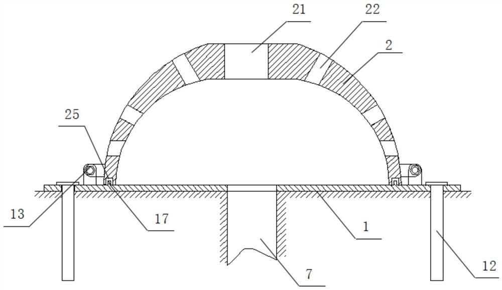
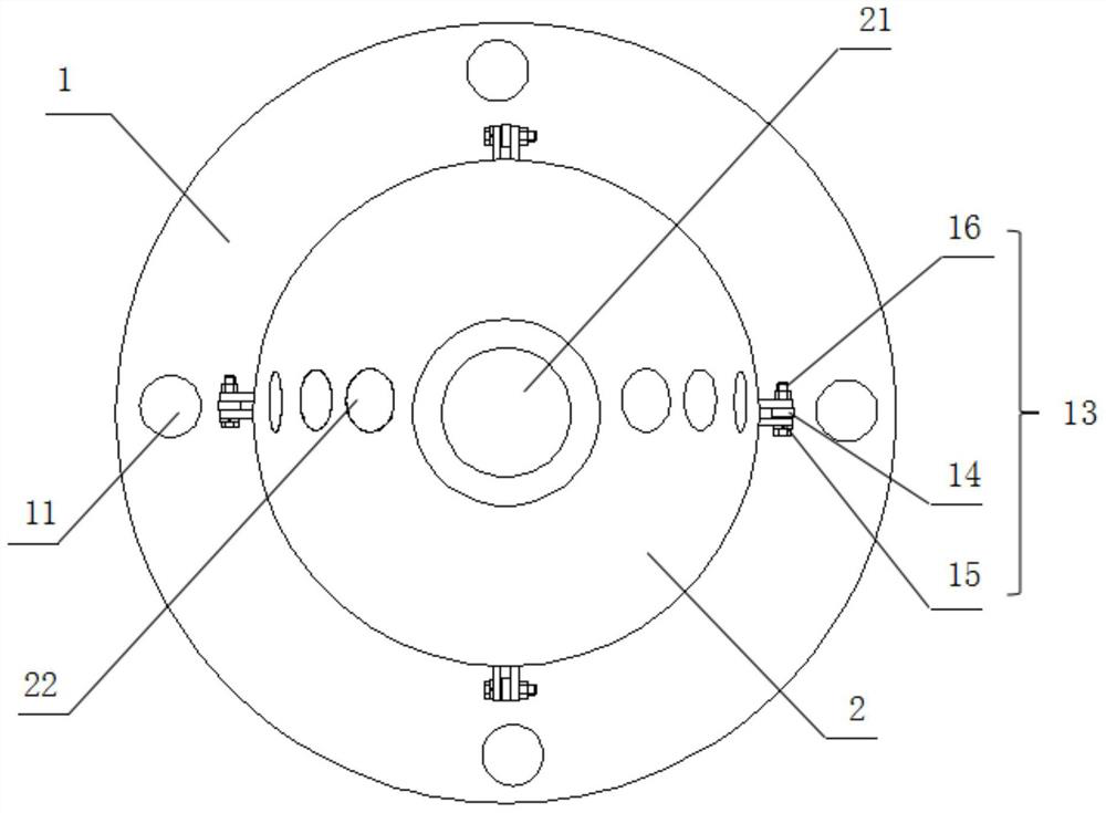
[0017] Please refer to Figure 1 to Figure 3 , an oil and gas leakage collection and constant pressure device, including a pressure bearing plate 1, a sealing device, a drilling fluid input box 41, a drilling fluid recovery box 42, a drill pipe 3, a constant pressure assembly, a petroleum gas collection assembly and a plurality of connecting pipes 24 , the pressure bearing plate 1 is arranged above the wellhead of the production well 7, the edge of the pressure bearing plate 1 is provided with four limiting holes 11, each of the limiting holes 11 is provided with a fixed pile 12, and the four The fixed piles 12 are all anchored on the ground around the production well 7, so that the pressure bearing plate 1 is anchored above the wellhead of the productio...


PUM


Abstract

The invention provides an oil gas leakage collection and constant-pressure device. The device comprises a pressure bearing plate and a closing cover, wherein the pressure bearing plate covers a well opening of an exploited well, the closing cover covers the pressure bearing plate, the closing cover is connected with a drilling fluid input box, a drilling fluid recycling box, an oil gas collectingbox and a constant-pressure assembly, a containing hole is formed in the top of the closing cover, a drill rod is arranged in the containing hole, the constant-pressure assembly is used for balancingpressure fluctuation of drilling fluid in the exploited well, and the oil gas collecting box is used for collecting gas spilled out of the exploited well. The device has the beneficial effects that the constant-pressure assembly connected with the closing cover can balance the pressure fluctuation of the drilling fluid in the exploited well, so that a pressure in the exploited well is kept unchanged, the danger of blowout in an oil gas exploitation process is avoided, the oil gas collecting box connected with the closing cover can collect oil gas and other greenhouse gases spilled out of the exploited well, so that the condition that the oil gas and other greenhouse gases leak from the exploited well and pollute the environment is avoided, and therefore, the oil gas exploitation process isgreen and environmentally friendly.

Description

technical field [0001] The invention relates to the field of oil extraction devices, in particular to an oil gas leakage collection and constant pressure device. Background technique [0002] Petroleum oil and gas extraction usually requires drilling rigs to drive drill pipes to drill production wells; during the drilling of production wells, the pressure of the drilling fluid inside will fluctuate due to pressure changes in the formation. When the pressure fluctuations of the drilling fluid in the production wells are too large, Blowouts are prone to occur in production wells, leading to safety issues. At the same time, during the drilling of production wells, a large amount of gas overflows from the production wells, and these gases are mainly petroleum gas and other greenhouse gases associated with petroleum liquids. Existing oil and gas extraction devices are difficult to solve the problems of petroleum gas leakage and excessive pressure fluctuation of drilling fluid. C...

Claims


Application Information

Patent Timeline
Patent Type & Authority Applications(China)
IPC IPC(8): E21B41/00E21B21/01
CPCE21B21/01E21B41/00E21B41/0021E21B41/005
Inventor 邓空刘占红武慧慧王杰郭伟汤冠雄高梦天吴少波徐飘飘江春雷古娟
Owner CHINA UNIV OF GEOSCIENCES (WUHAN)
Learn More