Internal combustion engine

A technology for internal combustion engines and crankshafts, which is applied in mechanical equipment, engine components, cooling of engines, etc.

Active Publication Date: 2020-10-09
HONDA MOTOR CO LTD
View PDF8 Cites 0 Cited by
  • Summary
  • Abstract
  • Description
  • Claims
  • Application Information

AI Technical Summary

Problems solved by technology

However, in the above-mentioned conventional internal combustion engine, an oil seal is provided between the bearing and the balancer drive gear, so the internal combustion engine tends to become larger in the axial direction of the crankshaft.
In addition, the thrust ac

Method used


Image

  • Internal combustion engine
  • Internal combustion engine
  • Internal combustion engine

Examples


Embodiment Construction

[0040] Hereinafter, embodiments of the present invention will be described with reference to the drawings. In addition, in the description, descriptions of directions such as front, rear, left, and right, and up and down are the same as directions with respect to the vehicle body unless otherwise specified. In addition, the code|symbol "FR" shown in each figure shows the front of a vehicle body, the code|symbol "UP" shows the upper side of a vehicle body, and the code|symbol "LH" shows the left side of a vehicle body.

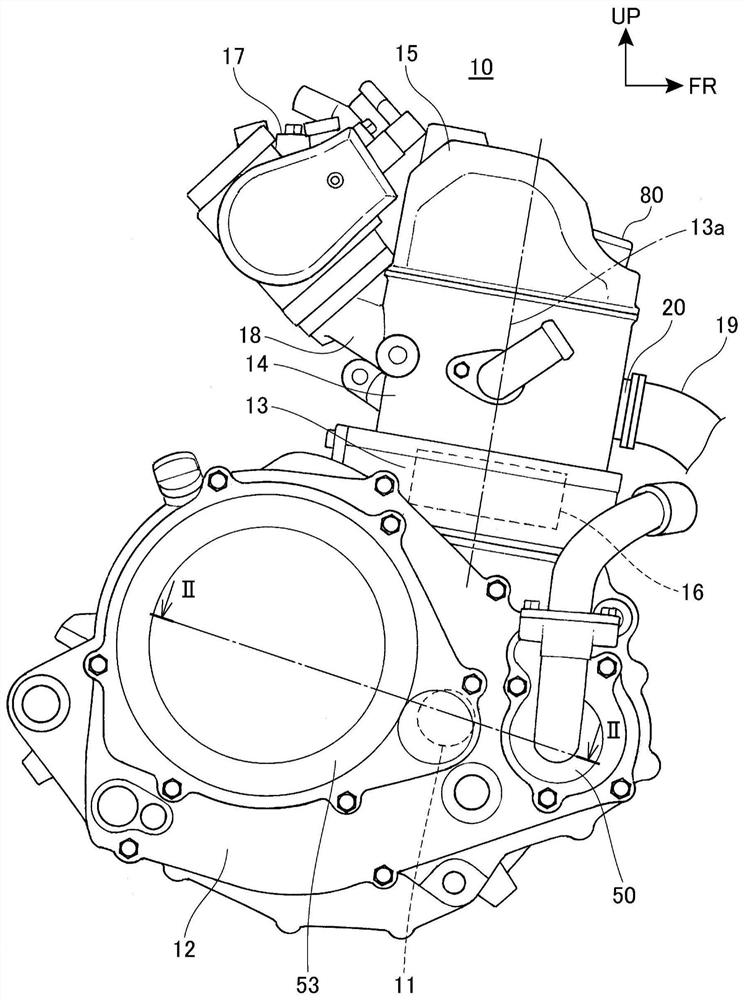
[0041] figure 1 It is the right side view of the internal combustion engine which concerns on embodiment of this invention.

[0042] The internal combustion engine 10 is mounted on a motorcycle. This motorcycle has: a frame (not shown), a front fork (not shown), which is supported on the front end of the frame, and a swing arm (not shown), which is freely supported on the vehicle The rear part of the frame; the front wheel (not shown) supported by the front fo...


PUM


Abstract

An internal combustion engine which is compact in the axial direction of a crankshaft and which can effectively bear pushing force acting on a one-way clutch mechanism. The internal combustion engineincludes: a crankshaft (11) supported via a bearing (35); a balancer drive gear (36); a balancer shaft (30); and a one-way clutch mechanism (37) that transmits to the crankshaft (11) a drive force tostart the internal combustion engine. In the internal combustion engine, the bearing (35) includes an oil seal (35d) built therein, the oil seal sealing a crank chamber (33) of the crankcase (12). Theone-way clutch mechanism (37) includes a case (55) fixed to the crankshaft (11) and a starter driven gear (56) provided relatively rotatably with respect to the case (55) and driven by the drive force. The starter driven gear (56) includes a thrust bearing portion (55e) that abuts on the balancer drive gear (36) in an axial direction of the crankshaft (11).

Description

technical field [0001] The present invention relates to internal combustion engines. Background technique [0002] Conventionally, an internal combustion engine is known, which includes: a crankshaft supported by a crankcase via a bearing; a balancer drive gear provided on the crankshaft; a balancer shaft provided with a balancer; and a balancer driven gear, It is provided on the balancer shaft and meshes with the balancer driving gear; and a one-way clutch mechanism, which transmits the driving force for starting the internal combustion engine to the crankshaft, and the balancer driving gear is arranged on the crankshaft between the bearing and the one-way clutch mechanism ( For example, refer to Patent Document 1). In Patent Document 1, an oil seal that seals the crank chamber is provided between the bearing and the balancer drive gear. [0003] prior art literature [0004] Patent Document 1: Japanese Patent Laid-Open No. 2009-209969 [0005] In addition, in an intern...

Claims


Application Information

Patent Timeline
IPC IPC(8): F16F15/26F02N15/02F02B63/06
CPCF16F15/262F02N15/02F02N15/022F02B63/06F16C9/02F16C41/001F02F7/0053F02F2001/245F02F1/38F02F7/0039F02N11/00F02N15/006F01P5/12F16F15/264F16C3/06
Inventor 畑江亮星野雅一
Owner HONDA MOTOR CO LTD
Why Eureka
Try Eureka