Hydrodynamic bearing device
a bearing device and hydrodynamic technology, applied in sliding contact bearings, manufacturing tools, instruments, etc., can solve the problems of increasing the number of components correspondingly, increasing the electric current consumption at the low temperature, etc., to prevent the reduction of the rigidity of the radial bearing, the effect of reducing the pressure inside the bearing and enhancing reliability
- Summary
- Abstract
- Description
- Claims
- Application Information
AI Technical Summary
Benefits of technology
Problems solved by technology
Method used
Image
Examples
first embodiment
(First Embodiment)
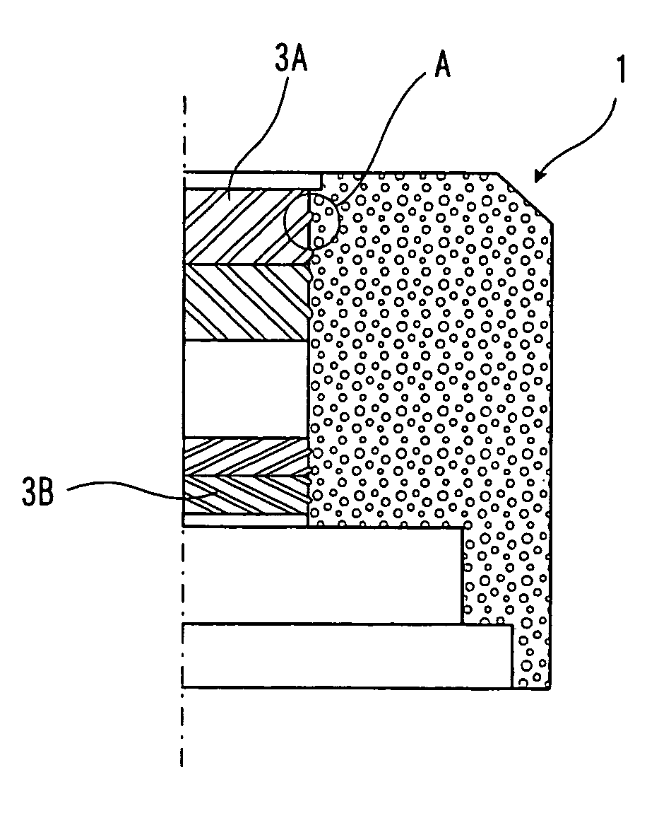
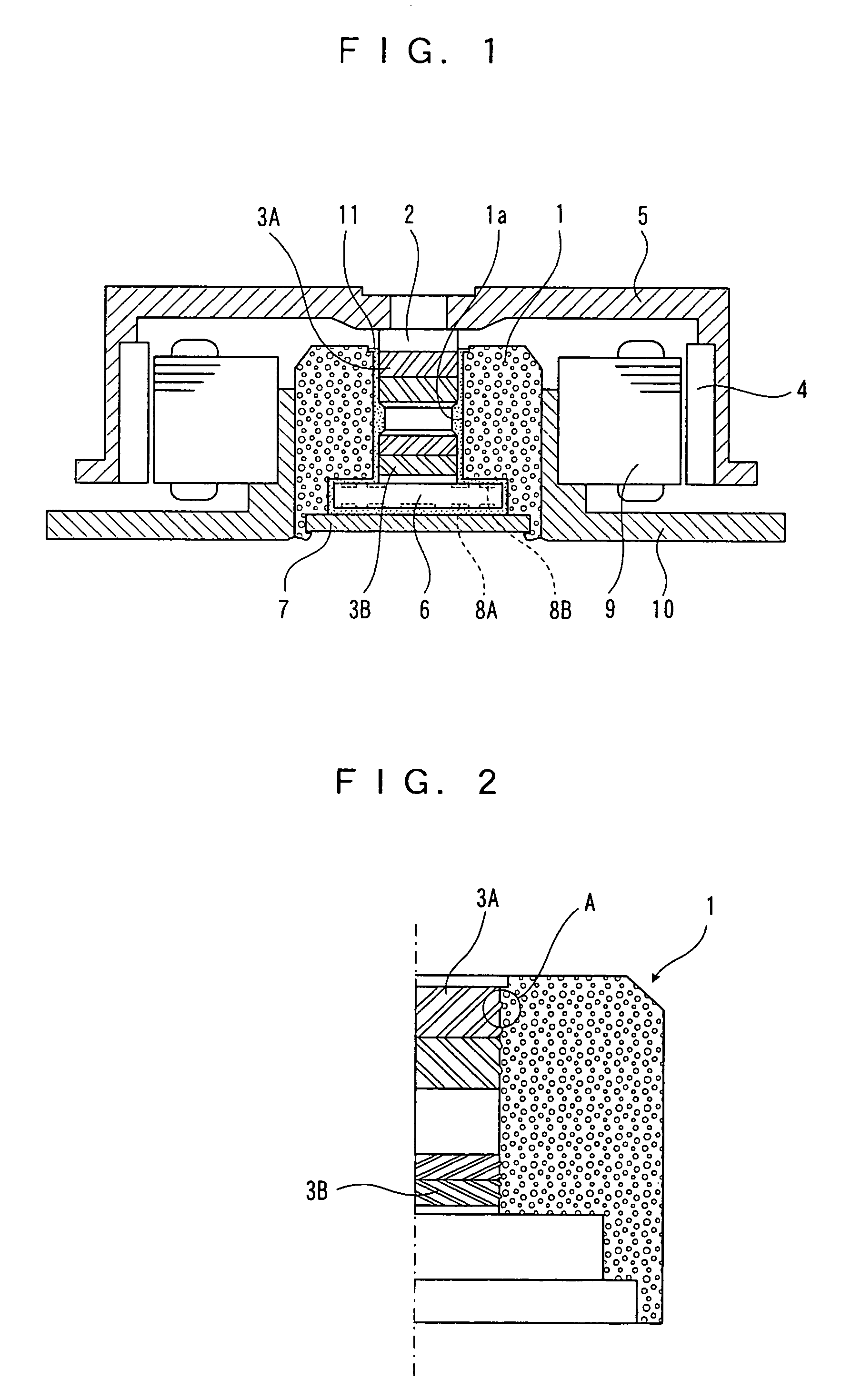
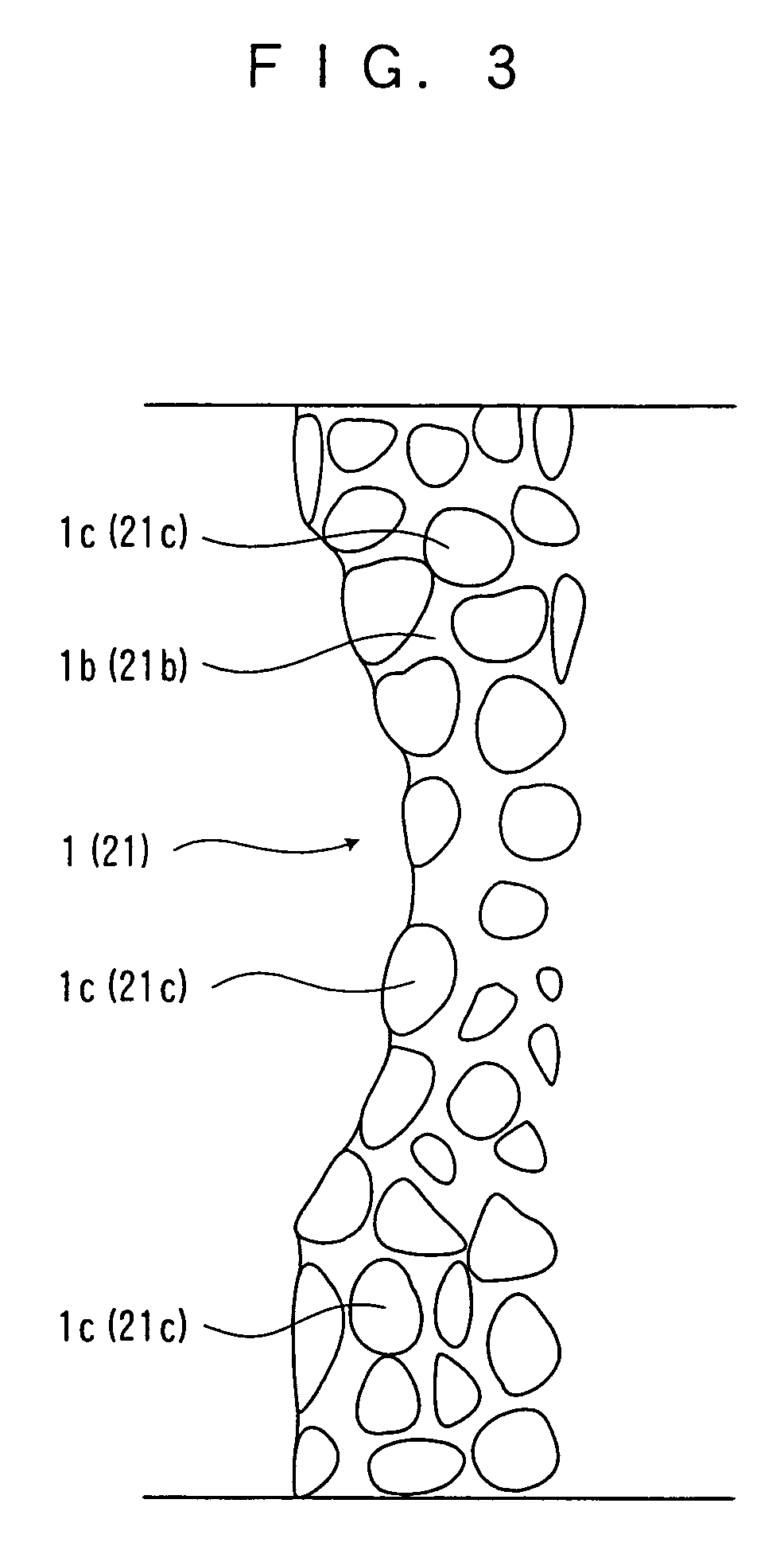
[0036]FIG. 1 is a sectional view of a hydrodynamic bearing device according to a first embodiment of the present invention. A shaft 2 is rotatably inserted into a bearing hole 1a of a sleeve 1, and a radial bearing surface having dynamic pressure generating grooves 3A and 3B constituted of pattern-shaped shallow grooves is provided at least one of an outer peripheral surface of the shaft 2 and an inner peripheral surface of the sleeve 1. A rotor hub 5 having a rotor magnet 4 in an inner periphery of its large diameter portion is mounted at one end (upper part in FIG. 1) side of the shaft 2, and a thrust flange 6 is integrally mounted at the other end (lower part in FIG. 1) side of the shaft 2 to be perpendicular to the shaft 2. A bearing surface at the lower end side of the thrust flange 6 opposes to a thrust plate 7, and the thrust plate 7 is fixed to the sleeve 1. A dynamic pressure generating groove 8A in a spiral or a herringbone pattern is formed on at least o...
second embodiment
(Second Embodiment)
[0052]FIG. 8 is a sectional view of a hydrodynamic bearing device according to a second embodiment of the present invention. A shaft 22 is rotatably inserted into a bearing hole 21a of a sleeve 21, and a radial bearing surface having dynamic pressure generating grooves 23A and 23B constructed by pattern-shaped shallow grooves is provided on at least one of an outer peripheral surface of the shaft 22 and an inner peripheral surface of the sleeve 21. A thrust bearing surface is formed at a lower end surface of the shaft 22 to be perpendicularly to the shaft 22, the thrust bearing surface is opposed to a thrust plate 24, the thrust plate 24 is fixed to the sleeve 21, a dynamic pressure generating groove 25 in a spiral or a herringbone pattern is formed on any one of the thrust bearing surface and the surface of the thrust plate 24, and a gap between the shaft 22 and the sleeve 21 and a gap between the shaft 22 and the thrust plate 24 are filled with oil 26 as the lub...
PUM
| Property | Measurement | Unit |
|---|---|---|
| dynamic pressure | aaaaa | aaaaa |
| weight | aaaaa | aaaaa |
| speed | aaaaa | aaaaa |
Abstract
Description
Claims
Application Information
 - R&D
- Intellectual Property
- Life Sciences
- Materials
- Tech Scout
- Unparalleled Data Quality
- Higher Quality Content
- 60% Fewer Hallucinations
Browse by: Latest US Patents, China's latest patents, Technical Efficacy Thesaurus, Application Domain, Technology Topic, Popular Technical Reports.
© 2025 PatSnap. All rights reserved.Legal|Privacy policy|Modern Slavery Act Transparency Statement|Sitemap|About US| Contact US: help@patsnap.com


