Tunnel gushing body excavation method

A technology of inrush and tunnel, which is applied in the field of tunnel inrush excavation, can solve problems such as construction difficulties, poor slope stability, and poor integrity, and achieve the goals of improving construction progress and safety, low excavation cost, and fast construction progress Effect

Active Publication Date: 2021-06-18
THE 3RD ENG CO LTD OF CHINA RAILWAY 16TH BUREAU GRP CO LTD +1
View PDF8 Cites 0 Cited by
  • Summary
  • Abstract
  • Description
  • Claims
  • Application Information

AI Technical Summary

Problems solved by technology

[0002] During the construction of the tunnel, some areas with complex geological conditions are often passed through. The surrounding rock is seriously deformed, squeezed and wrinkled, the integrity is extremely poor, the rock mass is broken, the stability of the slope is poor, and the grade of the tunnel surrounding rock is low. The risk of water inrush is extremely high. At present, most of the prevention methods for mud inrush and water inrush are to pre-reinforce the surrounding rock of Zhangzi face. However, due to the complexity of geological conditions, the deviation of geological forecast and the design Limitations: Mud and water inrush occur from time to time. Once it occurs, the inrush body will fill tens of meters to hundreds of meters behind the face, which brings great difficulties to the construction. At present, there is no good solution for the outburst. Therefore, how to excavate the inrush safely and efficiently has become particularly important for dealing with mud and water inrush areas

Method used


Image

  • Tunnel gushing body excavation method

Examples


Embodiment Construction

[0027] The present invention will be further described in detail below with reference to the accompanying drawings and specific embodiments.

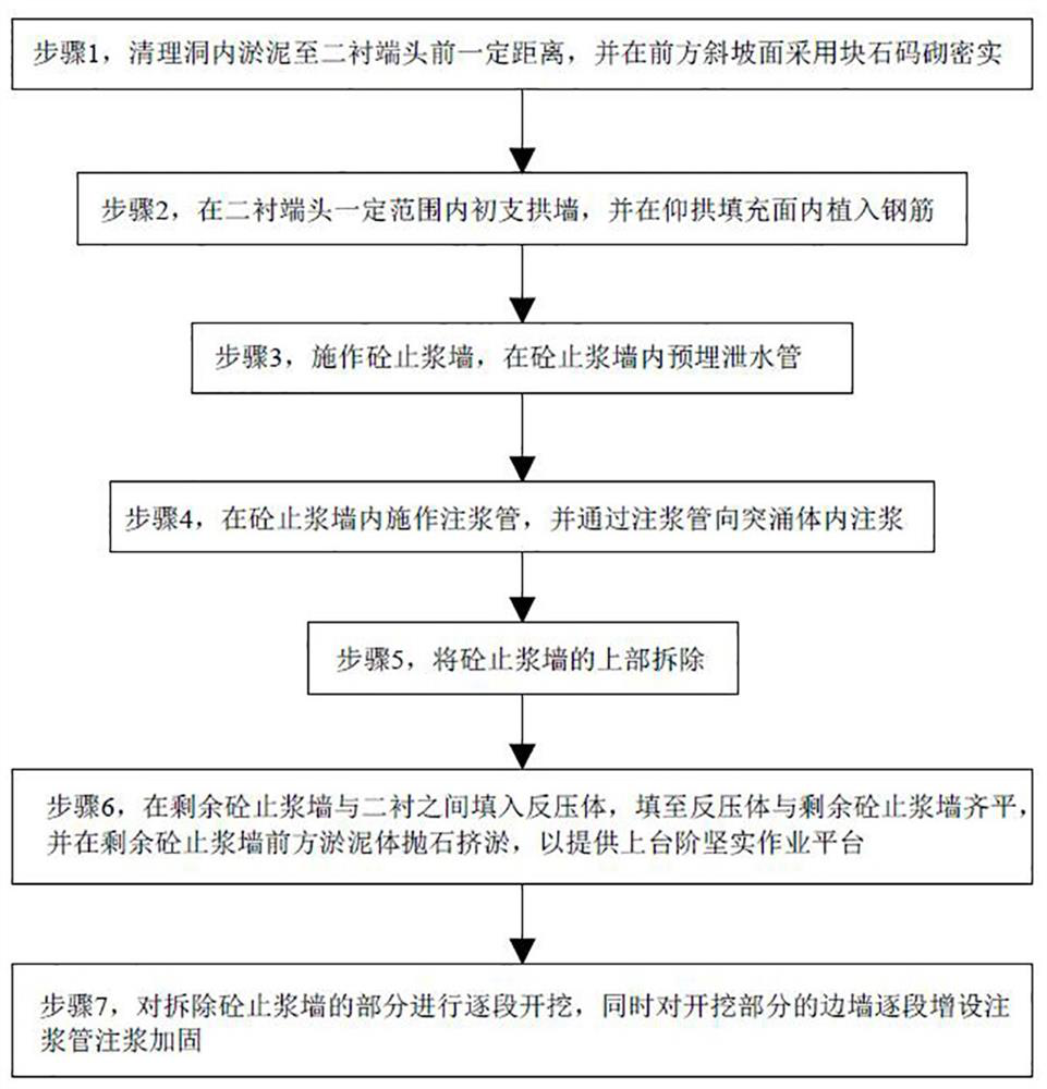
[0028] A method for excavating a tunnel inrush body includes three stages:

[0029] The first stage

[0030] Step 1. Clean up the silt in the cave to 2m before the end of the second lining (D1K78+904), and use block stones to build densely on the front slope;

[0031] Step 2. Plant C20 steel bars on the first support arch wall and invert arch filling surface within 2m of the end of the second lining. The length of the steel bars is 80cm (50cm implanted, 30cm exposed) and the spacing is arranged in a plum blossom shape of 30cm*30cm;

[0032] Step 3. Make a 2m thick C20 concrete grout stop wall, and pre-buy two rows (no less than 8, 3 above and 5 below) drainage pipes in the grouting wall, and the diameter of the pipes is not less than 100mm;

[0033] Step 4. Apply 1.0m*1.0m spaced advanced horizontal grouting pipes (32 pieces in total)...


PUM


Abstract

The invention provides a tunnel gushing body excavation method, and belongs to the technical field of tunnel gushing body excavation. The method comprises the following steps that 1, sludge in a tunnel is cleared to a certain distance in front of a second lining end, and a front slope surface is piled and compacted by adopting rock blocks; 2, an arch wall is preliminarily supported at the second lining end, and steel bars are implanted into an inverted arch filling surface; 3, a concrete grout stop wall is constructed, and a water drain pipe is pre-buried in the concrete grout stop wall; 4, a grouting pipe is constructed in the concrete grout stop wall, and grouting is carried out in a gushing body through the grouting pipe; 5, the upper part of the concrete grout stop wall is disassembled; 6, a back pressure body is filled between the remaining concrete grout stop wall and a second lining until the back pressure body is flush with the remaining concrete grout stop wall, and stone throwing and sludge squeezing are carried out on sludge in front of the remaining concrete grout stop wall; and 7, the part with the concrete grout stop wall disassembled is excavated section by section, and meanwhile, grouting pipes are additionally arranged on the side wall of the excavated part section by section for grouting reinforcement. According to the method, the gushing body can be safely and effectively excavated, and the phenomenon of water inrush and sludge inrush is avoided.

Description

technical field [0001] The invention relates to the technical field of tunnel inrush body excavation, in particular to a tunnel inrush body excavation method. Background technique [0002] In the process of tunnel construction, it often passes through some areas with complex geological conditions. The surrounding rock is severely deformed, squeezed and wrinkled, the integrity is extremely poor, the rock mass is broken, the slope stability is poor, and the surrounding rock level of the tunnel is low. The risk of water inrush is extremely high. At present, most of the prevention methods for mud and water inrush are pre-reinforcing the surrounding rock of Zhangzi face. Due to limitations, the phenomenon of mud and water inrush occurs from time to time. Once it occurs, the inrush body will fill up to several tens of meters to hundreds of meters behind the face, which will bring great difficulties to the construction. Therefore, how to excavate the inrush body safely and efficie...

Claims


Application Information

Patent Timeline
Patent Type & Authority Applications(China)
IPC IPC(8): E21D9/00E21D11/10
CPCE21D9/00E21D11/107Y02E10/20
Inventor 王泽坤田伟权王凤喜王蕾冯彪林克吴量
Owner THE 3RD ENG CO LTD OF CHINA RAILWAY 16TH BUREAU GRP CO LTD
Why Eureka
Try Eureka