Magnetic flux leakage driving type heat dissipation oil tank of transformer

A drive type, transformer technology, applied in the direction of transformer/inductor cooling, transformer/inductor components, transformer/inductor coil/winding/connection, etc., can solve the problems of slow passive heat dissipation and high energy consumption, and achieve increased The effect of airflow contact heat exchange speed, saving electric energy and increasing heat dissipation speed

Inactive Publication Date: 2020-10-09
孙亚林
View PDF0 Cites 0 Cited by
  • Summary
  • Abstract
  • Description
  • Claims
  • Application Information

AI Technical Summary

Problems solved by technology

[0004] The purpose of the present invention is to solve the disadvantages of slow passive heat dissipation, active need of independ

Method used


Image

  • Magnetic flux leakage driving type heat dissipation oil tank of transformer
  • Magnetic flux leakage driving type heat dissipation oil tank of transformer

Examples


Example Embodiment

[0017] The technical solutions in the embodiments of the present invention will be clearly and completely described below with reference to the accompanying drawings in the embodiments of the present invention. Obviously, the described embodiments are only a part of the embodiments of the present invention, but not all of the embodiments.

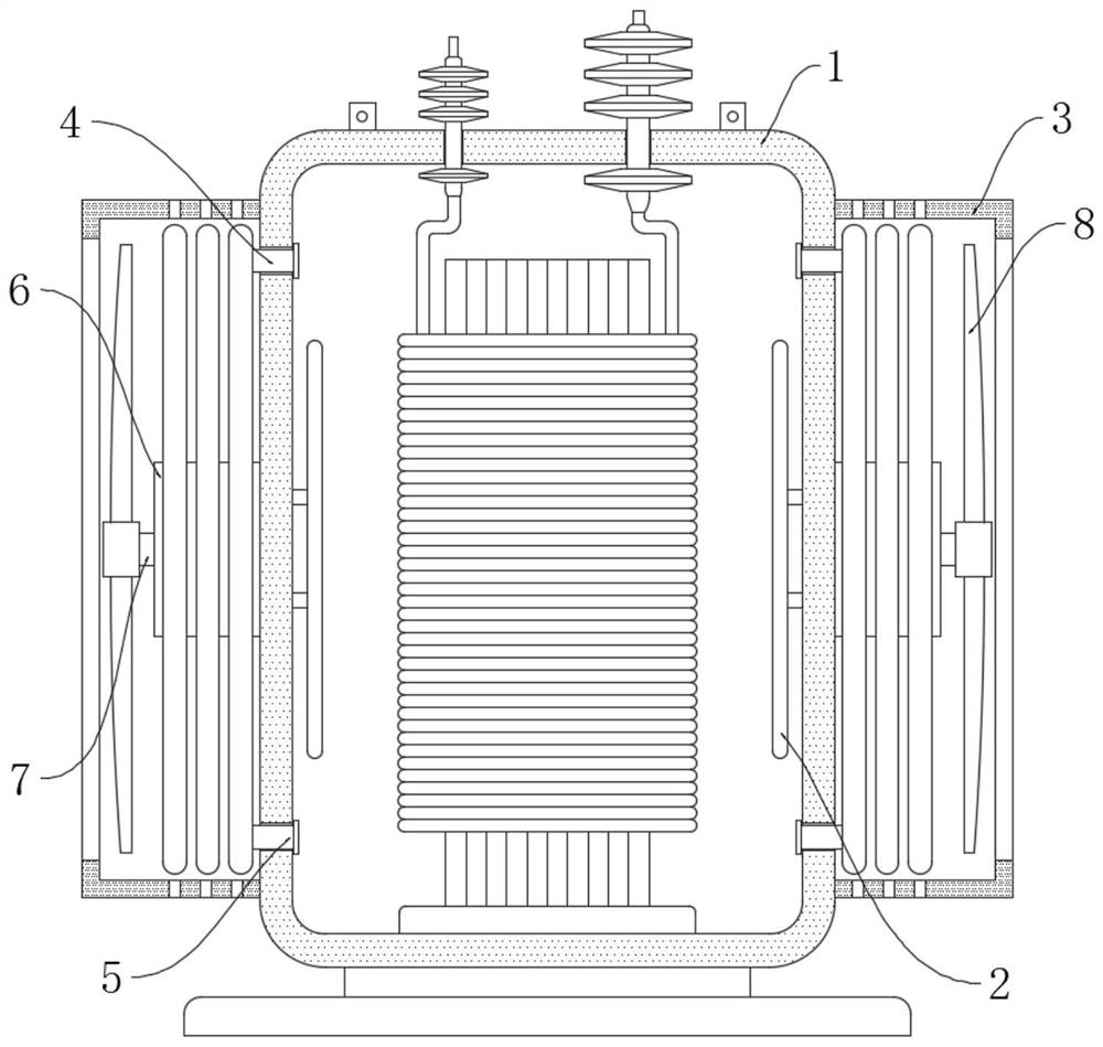
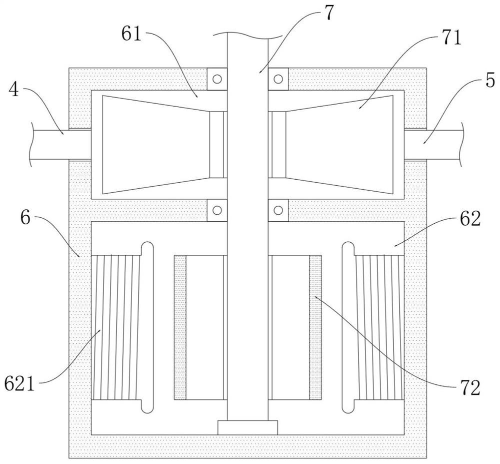
[0018] refer to Figure 1-2 , a transformer leakage magnetic drive type heat-dissipating oil tank, including a box body 1, two porous shields 3 are symmetrically installed on the outer side wall of the box body 1, and the inner upper and lower walls of each porous shield 3 are respectively stacked with oil suction pipes. 4 and the oil discharge pipe 5, two electromagnetic oil pumps 6 are symmetrically installed on the outer side wall of the box 1, one end of the oil suction pipe 4 and the oil discharge pipe 5 are installed on the electromagnetic oil pump 6, and the oil discharge pipe 5 of the oil suction pipe 4 is far away from the electroma...


PUM


Abstract

The invention discloses a magnetic flux leakage driving type heat dissipation oil tank of a transformer. The magnetic flux leakage driving type heat dissipation oil tank comprises a tank body, whereintwo porous shields are symmetrically mounted on the outer side wall of the tank body; an oil pumping pipe and an oil discharging pipe are respectively stacked and coiled on the upper wall and the lower wall of the inner side of each porous protective cover; two electromagnetic oil pumps are symmetrically installed on the outer side wall of the tank body; one ends of the oil pumping pipes and oneends of the oil discharging pipes are both installed on the electromagnetic oil pumps; the sections, away from the electromagnetic oil pumps, of the oil discharging pipes and the oil pumping pipes areinstalled above the side wall of the tank body and below the side wall of the tank body respectively; and magnetic leakage induction coils are symmetrically installed on the inner wall of the tank body. The magnetic leakage induction coils convert magnetic leakage of the transformer into electric energy to enable a driving shaft to rotate, the driving shaft rotates to drive an airflow fan and animpeller fan to rotate so as to increase an airflow contact heat exchange speed and a transformer oil circulation heat dissipation speed, so active heat dissipation is achieved, electric energy is saved, and the size of the transformer is not increased.

Description

technical field [0001] The invention relates to the field of power transformers, in particular to a transformer flux leakage driven cooling oil tank. Background technique [0002] The transformer will generate a lot of heat during use. Rapid heat dissipation of the transformer can increase the working efficiency of the transformer. The transformer cooling oil tank can make the transformer core winding immersed in the transformer oil, which not only provides good insulation protection, but also protects the core. Winding for heat dissipation. [0003] Existing transformer oil tanks usually use passive heat dissipation, that is, heat sinks or heat pipes are used for heat dissipation, and the heat dissipation speed is slow. Active heat dissipation requires the addition of active heat dissipation power modules, which not only increases the volume of the transformer, but also consumes a lot of power. Contents of the invention [0004] The purpose of the present invention is to...

Claims


Application Information

Patent Timeline
IPC IPC(8): H01F27/14H01F27/08H01F27/28H01F27/40H02K7/14
CPCH01F27/085H01F27/14H01F27/2876H01F27/40H02K7/14
Inventor 孙亚林王利利
Owner 孙亚林
Why Eureka
Try Eureka