
High-strength C-shaped bridge

A high-strength, bridge technology, applied in the direction of electrical components, can solve the problems of increased cost and manufacturing difficulty, low strength and load, unfavorable transportation and laying, etc., to facilitate independent or combined laying, save material consumption, and improve service life and the effect of the operating safety factor

Pending Publication Date: 2020-10-09
镇江市诚邦机械制造有限公司
View PDF0 Cites 0 Cited by
  • Summary
  • Abstract
  • Description
  • Claims
  • Application Information

AI Technical Summary

Problems solved by technology

In the prior art, the bridge frame with planar structure has low strength and load, especially the joint strength between the C-shaped side profile and the vertical surface of the bottom profile is not high, and there is a phenomenon of stress deformation, which affects independent, combined or large-span especially The safety factor of laying in the heavy-load area, only by increasing the amount of profiles such as steel to increase the thickness of the bridge not only increases the cost and manufacturing difficulty, but also is not conducive to transportation and laying, which needs to be improved urgently

Method used


Image

  • High-strength C-shaped bridge
  • High-strength C-shaped bridge
  • High-strength C-shaped bridge

Examples


Embodiment Construction

[0028] The specific embodiments of the present invention will be further described below in conjunction with the accompanying drawings.

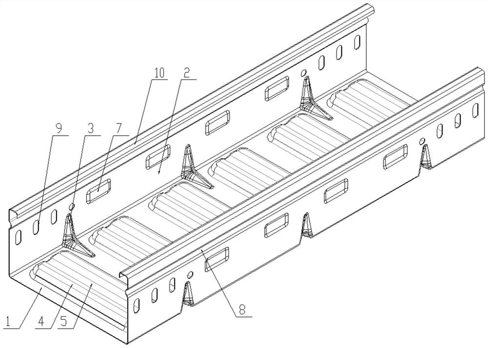
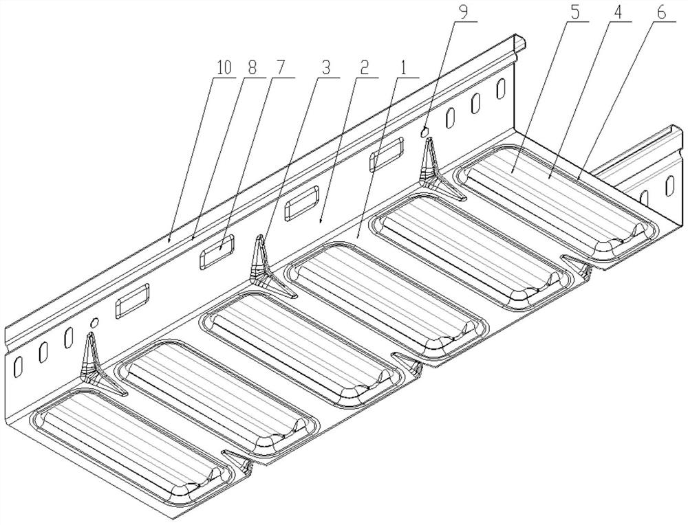
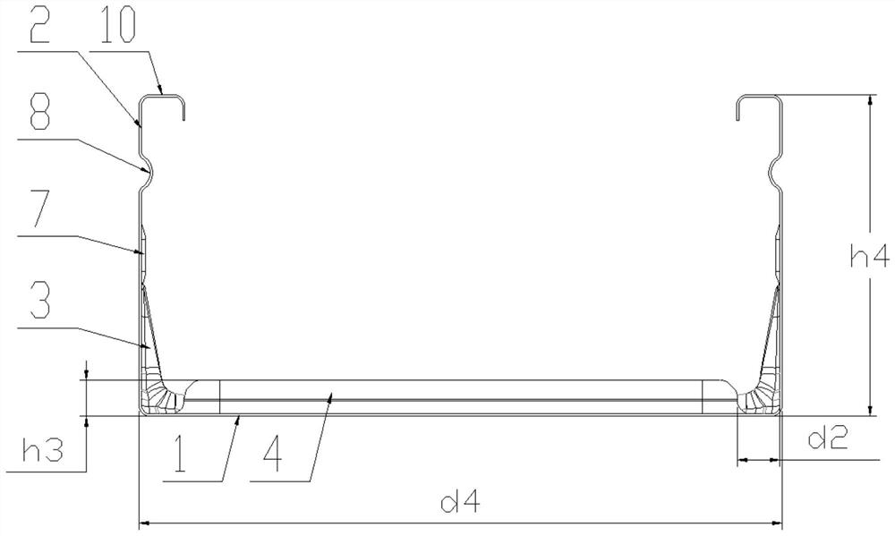
[0029] A high-strength C-shaped bridge frame includes a bottom profile 1 in an integrated C-shaped structure and a side profile 2 with both ends of the bottom profile 1 perpendicular to each other, wherein a number of spacings are arranged between the bottom profile 1 and the side profile 2, A corner convex hull 3 protruding to the inside of the bottom profile 1 and the side profile 2 is on the vertical surface of the bottom profile 1 and the side profile 2 and has the same thickness as the bottom profile 1 and the side profile 2;

[0030] The outer contour shape of the corner convex hull 3 coplanar with the bottom profile 1 or the side profile 2 is a triangle (see Picture 10 ), half waist type (see Picture 11 ) Or arc (see Picture 12 ), the convex depth of the corner convex plate on the symmetry plane of the bottom profile 1 and the side prof...


PUM

PropertyMeasurementUnit
Vertical heightaaaaaaaaaa
Heightaaaaaaaaaa

Abstract

The invention relates to a high-strength C-shaped bridge. The high-strength C-shaped bridge comprises a bottom profile and a side profile which are of an integrated C-shaped structure, wherein a plurality of corner convex hulls which are arranged at intervals and protrude towards the interiors of the bottom profile and the side profile are arranged between the bottom profile and the side profile;the corner convex hulls are located on the vertical surfaces of the bottom profile and the side profile; and a plurality of bottom ribs which are arranged at intervals and protrude towards the interior of the bottom profile are arranged on the bottom profile, convex ribs protruding towards the inside or the outside of the bottom profile are arranged at the centers of the bottom ribs, and blank holders correspondingly arranged outside the bottom ribs are arranged on the bottom profile, so a single-layer or double-layer reinforcing structure is formed. Under the condition that wall thickness isnot increased or material thickness is not reduced, the strength of the bottom profile is increased by the bottom ribs through mould pressing deformation, and the strength of the joint surface of thebottom profile and the side profile is increased by the corner convex hulls; and a size is reasonable, the weight, cost, stress, load and overall strength can be reduced, bridge transportation and independent or combined laying of the cable bridge are facilitated, service life is prolonged, operation safety coefficient is increased, and use requirements are met.

Description

Technical field [0001] The invention relates to a high-strength C-shaped bridge frame, which belongs to the technical field of bridge frames. Background technique [0002] Cable trays include trough-type cable trays, tray-type cable trays, stepped cable trays, grid trays, etc., which can be erected independently, or laid on various buildings and pipe gallery supports for laying cables, C-shaped cable trays The allowable stress meets the manager load such as the type and number of cables laid in the cable tray, the outer diameter weight / unit length of each cable, the dynamic load during construction and maintenance, and the additional load formed by ice, snow, wind and electromagnetic force. It directly affects the safety of bridge operation and combined laying deflection. In the prior art, the plane structure of the bridge frame has low strength and load, especially the bonding strength between the C-shaped side profile and the vertical surface of the bottom profile is not high,...

Claims


Application Information

Patent Timeline
IPC IPC(8): H02G3/04
CPCH02G3/0406H02G3/0437H02G3/0456
Inventor 时进专
Owner 镇江市诚邦机械制造有限公司
Learn More