
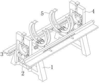
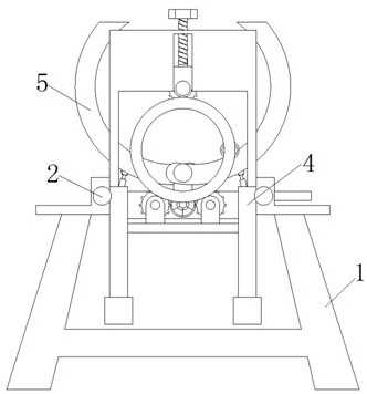
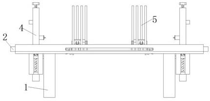
A kind of rod-shaped object binding device for construction engineering

A strapping device and technology for construction engineering, applied in the directions of strapping materials, strapping objects, packaging/bundling objects, etc., can solve the problems of increasing labor intensity of workers, reducing work efficiency, and weak strapping, etc., so as to be suitable for popularization and use and improve efficiency. , to avoid the effect of machine failure and difficult emergency braking

Inactive Publication Date: 2021-01-22
嵇贵美
View PDF5 Cites 0 Cited by
  • Summary
  • Abstract
  • Description
  • Claims
  • Application Information

AI Technical Summary

Problems solved by technology

[0004] The object of the present invention is to provide a binding device for rod-shaped objects in construction engineering. Through the use of a binding structure and a supporting structure, it solves the problem that the existing construction engineering rod-shaped objects need to be manually bundled. The binding is not firm and easy to loosen, which increases the labor force Intensity, time-consuming and labor-intensive, reducing work efficiency

Method used


Image

  • A kind of rod-shaped object binding device for construction engineering
  • A kind of rod-shaped object binding device for construction engineering
  • A kind of rod-shaped object binding device for construction engineering

Examples


Embodiment Construction

[0034] The following will clearly and completely describe the technical solutions in the embodiments of the present invention with reference to the accompanying drawings in the embodiments of the present invention. Obviously, the described embodiments are only some, not all, embodiments of the present invention. Based on the embodiments of the present invention, all other embodiments obtained by persons of ordinary skill in the art without creative efforts fall within the protection scope of the present invention.

[0035] In describing the present invention, it is to be understood that the terms "opening", "upper", "lower", "thickness", "top", "middle", "length", "inner", "surrounding" etc. Indicating orientation or positional relationship is only for the convenience of describing the present invention and simplifying the description, and does not indicate or imply that the components or elements referred to must have a specific orientation, be constructed and operated in a sp...


PUM


Abstract

The invention discloses a rod-shaped object binding device for construction engineering, and relates to the technical field of construction engineering binding. The rod-shaped object binding device comprises a base; fixed rods are fixed to the upper surface of the base; a rectangular groove is formed in one surface of each fixed rod; fixed blocks are fixed inside the rectangular grooves; first driving mechanisms are installed on both sides of the fixed rods respectively; output shaft ends of the first driving mechanisms penetrate through the fixed rods and extend into the fixed rods; first threaded rods rotationally connected with the fixed blocks are fixed to the output shaft ends of the first drive mechanisms; binding structures are in threaded connection onto the outer surfaces of the first threaded rods and positioned between the two adjacent fixed rods, and comprise sliding plates; and sliding blocks matched with the first threaded rods are fixed to the two sides of the sliding plates. The rod-shaped object binding device solves the problems that rod-shaped objects of the existing construction engineering need to be manually bound through the use of the binding structures anda supporting structure, so that the rod-shaped objects are not firm and likely to loosen, the labor intensity of workers is increased, time and labor are saved, and the work efficiency is reduced.

Description

technical field [0001] The invention belongs to the technical field of construction engineering binding, in particular to a binding device for rod-shaped objects used in construction engineering. Background technique [0002] Construction engineering refers to the planning, survey, design and construction, completion and other technical work of new construction, reconstruction or expansion of buildings and ancillary structures and facilities, as well as the completed engineering entities and the installation of supporting lines, pipelines and equipment. It also refers to the construction of various houses and buildings, also known as construction workload. With the rapid development of society, the construction industry is also rapidly rising. [0003] In the process of building new construction, reconstruction and expansion, it is often necessary to pack and bundle some rod-shaped objects, such as steel bars and plastic pipes, etc., but the existing rod-shaped objects often...

Claims


Application Information

Patent Timeline
Patent Type & Authority Patents(China)
IPC IPC(8): B65B13/20B65B13/18B65B13/12
CPCB65B13/12B65B13/184B65B13/20
Inventor 嵇贵美
Owner 嵇贵美
Learn More