Distributor and main shaft

A distributor and seat technology, which is applied in distribution devices, engine components, engine lubrication, etc., can solve the problem of difficult quantitative transportation of oil bodies, inability to supply different oil quantities, and inability to adjust the oil output of quantitative oil and gas distributors, etc. question

Pending Publication Date: 2020-10-13
GUANGZHOU HAOZHI ELECTROMECHANICAL
View PDF0 Cites 0 Cited by
  • Summary
  • Abstract
  • Description
  • Claims
  • Application Information

AI Technical Summary

Problems solved by technology

[0003] The oil-air distributor is a key component of the oil-air lubrication device. The existing oil-air distributor mainly realizes quantitative distribution by controlling the pumping time, but it is difficult to ensure equal pumping oil pressure at each time, so it is difficult to achieve oil-air lubrication in each working cycle. Quantitative delivery of the body; in addition, the oil volume output of each quantitative oil and gas distributor cannot be adjusted, which cannot meet the different oil volumes supplied to the bearings of different types of main shafts

Method used


Image

  • Distributor and main shaft
  • Distributor and main shaft
  • Distributor and main shaft

Examples


Embodiment Construction

[0044] Preferred embodiments of the present application will be described in detail below with reference to the accompanying drawings. Those skilled in the art will appreciate that these descriptions are only descriptive and exemplary, and should not be construed as limiting the protection scope of the present application.

[0045] First of all, it should be noted that the orientations of top, bottom, upward, and downward mentioned in this article are defined relative to the directions in each drawing, and they are relative concepts, and therefore can be It changes in different positions and different practical states. Accordingly, these or other orientations should not be construed as limiting terms. In addition, the "front" and "rear" in this embodiment are defined relative to the upstream and downstream of the oil passage, wherein the front end is near the upstream end, and the rear end is near the downstream end.

[0046] It should be noted that the term "comprising" doe...


PUM


Abstract

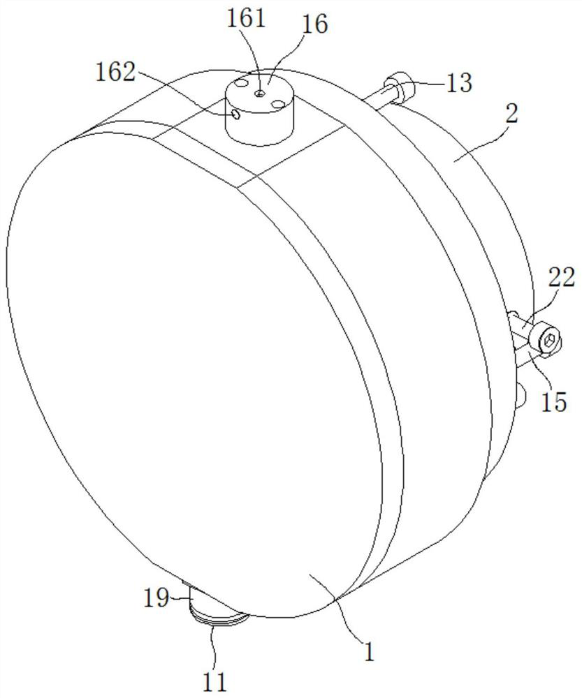
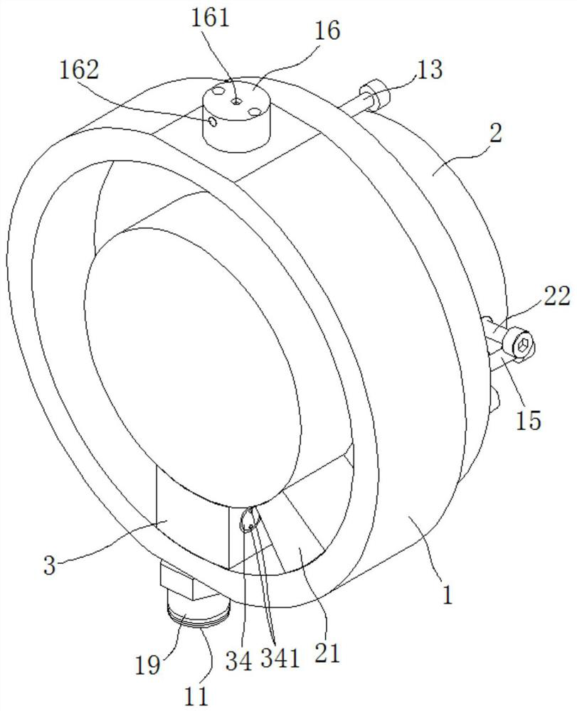
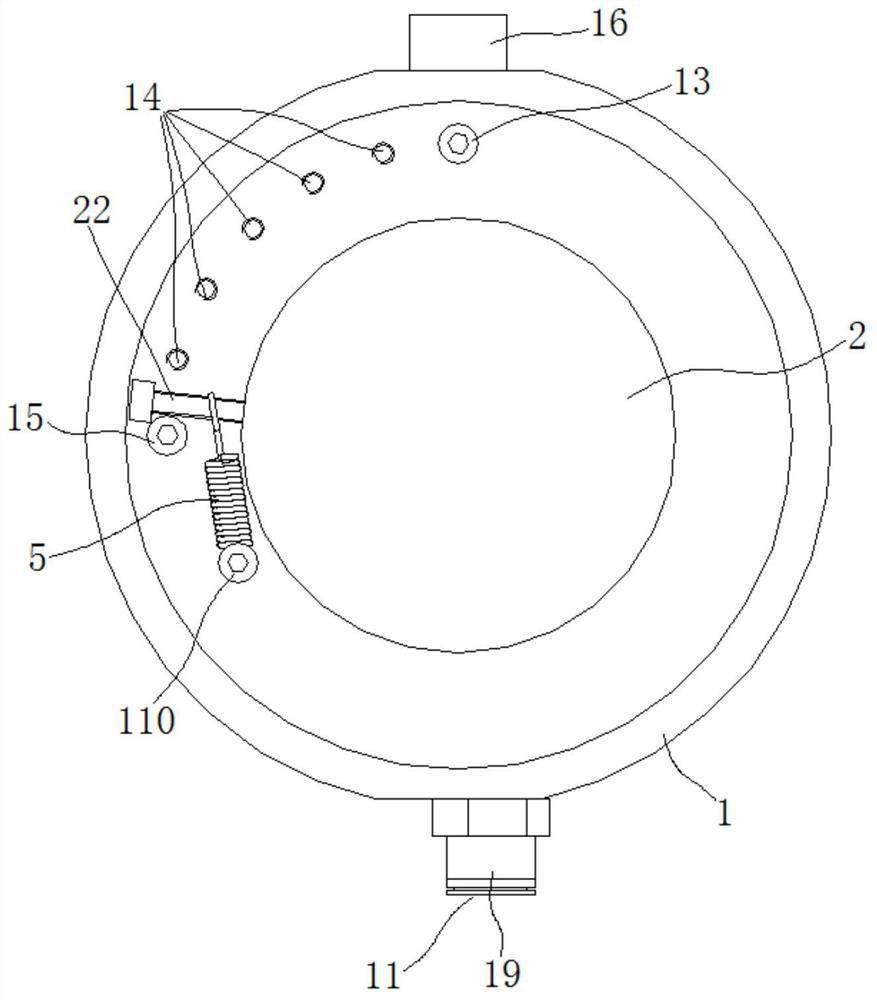
The invention discloses a distributor and a main shaft. The distributor comprises a distributor base, a rotary shaft and an oil inlet assembly, wherein an oil inlet and an oil outlet are formed in thedistributor base; the rotary shaft is rotatably mounted in the distributor base through an elastic return part; an oil cavity which surrounds the rotary shaft is defined between the rotary shaft andthe distributor base; a baffle block is mounted on the rotary shaft; a limiting mechanism capable of limiting a rotation angle of the rotary shaft is arranged between the rotary shaft and the distributor base; the oil inlet assembly is mounted on the distributor base, and is arranged in an accommodating cavity by spacing the baffle block in a peripheral direction; the baffle block and the oil inlet assembly are used for dividing the oil cavity into an oil pressure cavity and an oil storage cavity; an oil path is arranged in the oil inlet assembly; the two ends of the oil path are separately anoil inlet end and an oil outlet end; the oil inlet end communicates with the oil inlet, and the oil outlet end communicates with the oil storage cavity; and a spring, a valve plug and an oil path converter are arranged in the oil path. The oil pressure cavity can be communicated while the oil inlet pumps high-pressure oil, and the oil storage cavity can be communicated while oil supply is disconnected. The distributor has the beneficial effect of being capable of realizing stable oil quantitative output.

Description

technical field [0001] The invention relates to an oil and gas distributor and a main shaft including the same. Background technique [0002] The application of oil-air lubrication technology to the main shaft is an efficient lubrication method after grease lubrication and oil mist lubrication technology. It mainly uses compressed air as power to continuously and accurately provide a small amount of lubricating oil to the bearing of the main shaft, which can improve The limit speed of the bearing and increase the operating life of the bearing. [0003] The oil-air distributor is a key component of the oil-air lubrication device. The existing oil-air distributor mainly realizes quantitative distribution by controlling the pumping time, but it is difficult to ensure equal pumping oil pressure at each time, so it is difficult to achieve oil-air lubrication in each working cycle. Quantitative delivery of the body; in addition, the oil volume output of each quantitative oil and ...

Claims


Application Information

Patent Timeline
IPC IPC(8): F16N25/04F16N7/36F16N27/00
CPCF16N7/36F16N25/04F16N27/00
Inventor 伍曦张翰乾汤丽君汤秀清
Owner GUANGZHOU HAOZHI ELECTROMECHANICAL
Why Eureka
Try Eureka