Low-nitrogen and high-efficiency condensing boiler

A condensing boiler, high-efficiency technology, applied in air heaters, combustion methods, gas fuel burners, etc., can solve the problems of inability to absorb the latent heat of flue gas vaporization, inability to achieve efficient heat exchange, and high flue gas outlet temperature, and to meet the The effect of free expansion, increased flow distance, and increased heat exchange efficiency

Pending Publication Date: 2020-10-13
QINGDAO FERROLI HEATING & VENTILATION & TEMPERATURE CONTROL TECH EQUIP MFG CO LTD
View PDF0 Cites 0 Cited by
  • Summary
  • Abstract
  • Description
  • Claims
  • Application Information

AI Technical Summary

Problems solved by technology

[0003] However, the existing gas-fired boiler still has the following defects: the design of the boiler body and the smoke pipe in the existing boiler makes the heat exchange effect between the flue gas and water in the furnace poor; the two heat exchange media in the existing boiler are mostly the same flow in the opposite direction, resulting in high flue gas outlet temperature, unable to absorb the latent heat of vaporization in the flue gas, and failing to achieve efficient heat exchange

Method used


Image

  • Low-nitrogen and high-efficiency condensing boiler
  • Low-nitrogen and high-efficiency condensing boiler
  • Low-nitrogen and high-efficiency condensing boiler

Examples


Embodiment 1

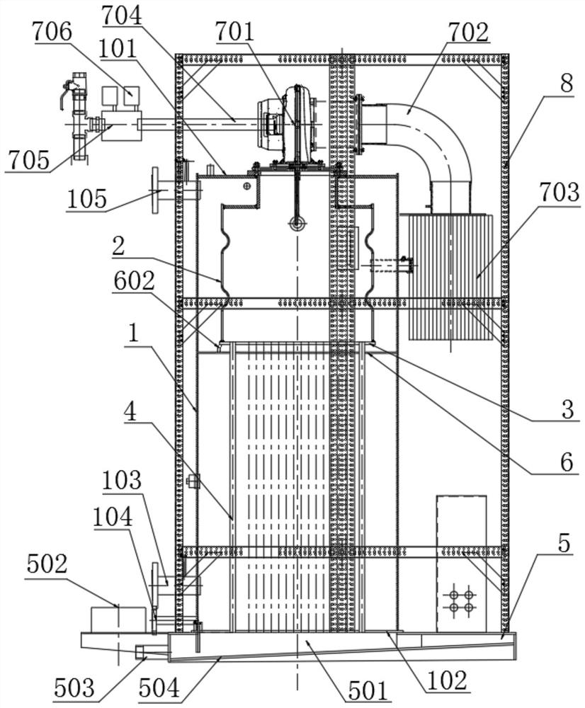
[0066] Such as figure 1 As shown, a low-nitrogen high-efficiency condensing boiler includes an outer casing and a boiler body located inside the outer casing;

[0067] The boiler body includes a vertical cylinder 1, the top of the vertical cylinder 1 is fixed with an upper end plate 101 with a middle opening, and the bottom of the vertical cylinder 1 is fixed with a lower tube plate 102;

[0068] A furnace 2 is arranged on the inner upper part of the vertical cylinder 1;

[0069] The top of the furnace 2 is provided with a fully premixed combustion assembly, and the bottom of the furnace 2 is fixed with an upper tube plate 3, and a number of vertical chimneys connected with the inner cavity of the furnace 2 are fixedly arranged on the upper tube plate 3. Tube 4; the bottom of the vertical smoke tube 4 is fixedly connected to the lower tube plate 102;

[0070] The bottom of the boiler body is provided with a base 5, the base 5 is provided with a smoke exhaust chamber 501 comm...

Embodiment 2

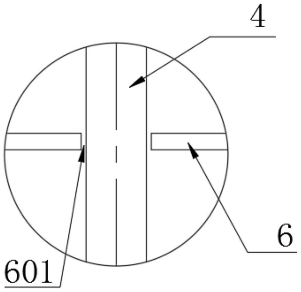
[0076] On the basis of Example 1, such as Figure 4-5 As shown, the inside of the vertical smoke pipe 4 is provided with a spoiler 401 that promotes the smoke to flow along the spiral direction, and the spoiler 401 extends from the inner upper part of the vertical smoke pipe 4 to the bottom;

[0077] The two side surfaces of the spoiler 401 are two parallel helical surfaces 402; two helical flue gas flows are formed between the two helical surfaces 402 of the spoiler 401 and the inner wall of the vertical smoke pipe 4. circulation channel.

[0078] Specifically, as Figure 6 As shown, the radial section of the spoiler 401 has a rectangular structure.

[0079] Specifically, the spoiler 401 is made of 316L stainless steel.

[0080] In this application, the spoiler 401 is easy to install. When installing, the formed spoiler 401 can be directly inserted into the vertical smoke pipe 4, so that the edge side wall of the spoiler 401 is close to the inner wall of the vertical smoke...

Embodiment 3

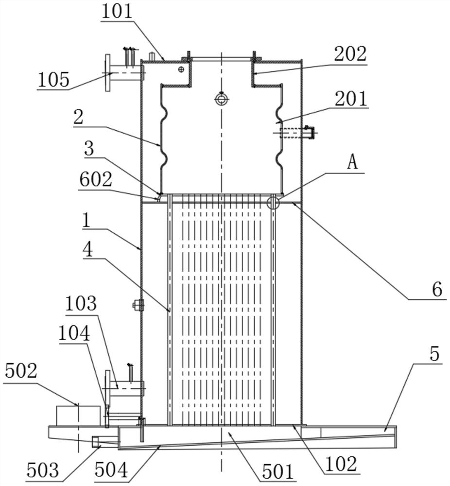
[0083] On the basis of embodiment 1 or embodiment 2, such as figure 2 As shown, the furnace 2 includes a main furnace 201, and the upper part of the main furnace 201 is coaxially provided with an auxiliary furnace 202;

[0084] The diameter of the auxiliary furnace 202 is smaller than the diameter of the main furnace 201;

[0085] The top of the auxiliary furnace 202 is fixedly connected to the side wall of the middle opening of the upper end plate 101 of the vertical cylinder 1 .

[0086] In the prior art, the furnace adopts a design with the same thickness up and down, and the top of the furnace is fixedly connected to the bottom of the upper end plate of the vertical cylinder. Since the diameter of the middle opening of the upper end plate of the vertical cylinder is smaller than the diameter of the furnace, the vertical A part of the upper end plate of the cylinder is located inside the furnace. When the boiler is running, the high temperature in the furnace will cause t...


PUM


Abstract

The invention discloses a low-nitrogen and high-efficiency condensing boiler. The low-nitrogen and high-efficiency condensing boiler comprises a shell body and a boiler body; the boiler body comprisesa vertical cylinder body, an upper end plate with an opening in the middle is fixedly arranged at the top of the vertical cylinder body, and a lower pipe plate is fixedly arranged at the bottom of the vertical cylinder body; a boiler furnace is arranged on the upper part of the inner side of the vertical cylinder body; a full premixed combustion assembly is arranged at the top of the boiler furnace, an upper pipe plate is fixedly arranged at the bottom of the boiler furnace, and a plurality of vertical smoke pipes are fixedly arranged on the upper pipe plate; a base is arranged at the bottomof the boiler body, an exhaust cavity is formed in the base, and an exhaust pipeline and a condensate water port are arranged on one side of the exhaust cavity; a water inlet and a sewage outlet are formed in the lower part of the side wall of the vertical cylinder body; and a water outlet is formed in the upper part of the side wall of the vertical cylinder body. According to the low-nitrogen andhigh-efficiency condensing boiler, due to the position arrangement of the water inlet and the water outlet, the flow direction of water is from bottom to top; the full prefixed combustion assembly, the boiler furnace and the vertical smoke pipe are arranged, so that the flow direction of the smoke is from top to bottom; and therefore, the water and smoke have the effect of countercurrent flow andheat exchange, and the sufficient and efficient heat exchange of the smoke and water is achieved.

Description

technical field [0001] The invention belongs to the technical field of boilers, and in particular relates to a low-nitrogen high-efficiency condensing boiler. Background technique [0002] The boiler is a kind of energy conversion equipment. The energy input to the boiler includes chemical energy and electric energy in the fuel, and the boiler outputs steam, high-temperature water or organic heat carrier with a certain amount of heat energy. With the increasingly stringent environmental protection requirements, the application of gas boilers is becoming more and more extensive. [0003] However, the existing gas-fired boiler still has the following defects: the design of the boiler body and the smoke pipe in the existing boiler makes the heat exchange effect between the flue gas and water in the furnace poor; the two heat exchange media in the existing boiler are mostly the same Flow in the opposite direction, resulting in high outlet temperature of the flue gas, unable to ...

Claims


Application Information

Patent Timeline
Patent Type & Authority Applications(China)
IPC IPC(8): F24H8/00F24H9/00F24H9/18F23D14/02F23D14/68F28F1/40F28F9/24
CPCF23D14/02F23D14/68F24H8/00F24H9/0005F24H9/1836F28F1/40F28F9/24Y02B30/00
Inventor 张厚吉侯俊成张雪芹张纪祥
Owner QINGDAO FERROLI HEATING & VENTILATION & TEMPERATURE CONTROL TECH EQUIP MFG CO LTD
Why Eureka
Try Eureka