Pollutant monitoring method and device, terminal equipment and storage medium

A technology for pollutants and pollutants, which is used in measurement devices, analysis of gas mixtures, prediction, etc. It can solve the problems of large analysis errors and inability to provide pollutant control plans in advance, and achieve the effect of avoiding analysis errors and high timeliness.

Active Publication Date: 2020-10-13
PINGAN INT SMART CITY TECH CO LTD
View PDF5 Cites 10 Cited by
  • Summary
  • Abstract
  • Description
  • Claims
  • Application Information

AI Technical Summary

Problems solved by technology

[0004] In view of this, the embodiment of the present application provides a pollutant monitoring method, device, terminal equipment and computer-readable storage medium to solve the problem of pollution in the prior art The analysis error of the precursor pollutants of pollutants is large and the control plan of pollutants cannot be given in advance

Method used


Image

  • Pollutant monitoring method and device, terminal equipment and storage medium
  • Pollutant monitoring method and device, terminal equipment and storage medium
  • Pollutant monitoring method and device, terminal equipment and storage medium

Examples


Embodiment 2

[0103] see Figure 4 , Figure 4 It is a structural block diagram of a pollutant monitoring device provided in the embodiment of the present application. In this embodiment, each unit included in the mobile terminal is used to execute Figure 1 to Figure 3 Each step in the corresponding embodiment. For details, please refer to Figure 1 to Figure 3 as well as Figure 1 to Figure 3 Related descriptions in the corresponding embodiments. For ease of description, only the parts related to this embodiment are shown. see Figure 4 , the pollutant monitoring device 40 includes:

[0104]The relationship curve generation module 401 is used to obtain the historical sample data of the target monitoring area, and generate the relationship curve between the concentration of pollutants in the target monitoring area and the precursor pollutants corresponding to the pollutants according to the historical sample data; The historical sample data includes historical monitoring data and p...

Embodiment 3

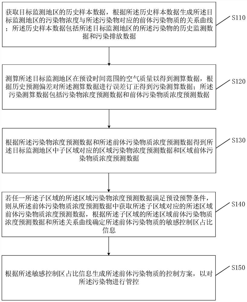
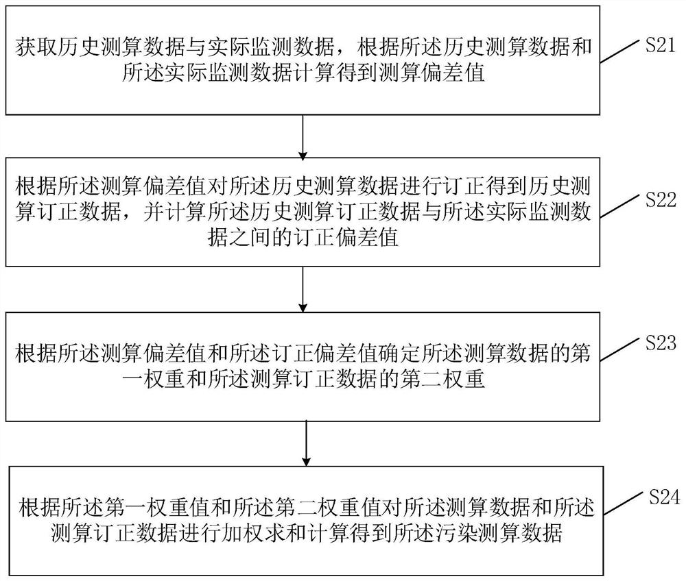
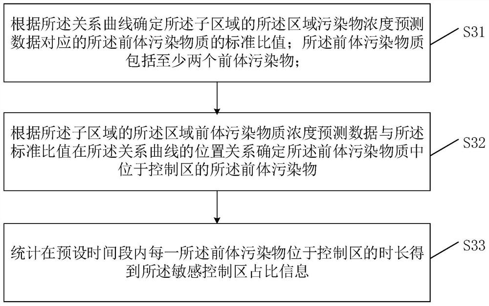
[0111] Figure 5 It is a structural block diagram of a terminal device provided by another embodiment of the present application. Such as Figure 5 As shown, the terminal device 50 of this embodiment includes: a processor 51, a memory 52, and a computer program 53 stored in the memory 52 and operable on the processor 51, such as a program of a pollutant monitoring method. When the processor 51 executes the computer program 73, it realizes the steps in the embodiments of the above-mentioned pollutant monitoring methods, for example figure 1 shown in S110 to S150, or figure 2 and image 3 S21 to S24 and S31 to S33 are shown. Or, when the processor 51 executes the computer program 53, the above-mentioned Figure 4 The function of each unit in the corresponding embodiment, for example, Figure 4 Functions of modules 401 to 405 shown, please refer to Figure 4 Relevant descriptions in the corresponding embodiments are not repeated here.

[0112] Exemplarily, the computer p...


PUM


Abstract

The invention is suitable for the technical field of artificial intelligence, and provides a pollutant monitoring method and device, terminal equipment and a storage medium, and the method comprises the steps: obtaining the historical sample data of a target monitoring region, and generating a relation curve between the pollutant concentration of the target monitoring region and a precursor pollutant according to the historical sample data; measuring and calculating the air quality of the target monitoring area in a preset time range to obtain measurement and calculation data, and performing error correction to obtain pollution measurement and calculation data; if the regional pollutant concentration prediction data of any sub-region meets a preset early warning condition, determining proportion information of a sensitive control region of the precursor pollutants according to the regional precursor pollutant concentration prediction data of the sub-region and the relation curve; and generating a precursor pollutant control scheme according to the proportion information of the sensitive control area. The problems that precursor pollutant analysis errors are large, and a pollutant control scheme cannot be given in advance are solved. In addition, the invention also relates to a blockchain technology.

Description

technical field [0001] The present application relates to the technical field of artificial intelligence, and in particular to a pollutant monitoring method, device, terminal equipment and computer-readable storage medium. Background technique [0002] Nowadays, photochemical smog pollution is becoming more and more common and serious in major industrial cities, among which ozone pollutant O 3 Accounting for more than 90%, it is an important indicator to measure photochemical smog, while volatile organic compounds (VOCs) and nitrogen oxides (NOx) are the 3 important precursor pollutants. From the mixture of different initial concentrations of VOCs and NOx as the starting condition, the ozone pollutant O can be calculated 3 daily maximum concentration, and get a range of ozone O 3 EKMA curves for isoconcentration curves. In the related art, the existing atmospheric ozone pollution control method is based on the concentration of the precursor pollutants VOCs and NOx in the...

Claims


Application Information

Patent Timeline
Patent Type & Authority Applications(China)
IPC IPC(8): G06Q10/04G06Q50/26G01N33/00
CPCG06Q10/04G06Q50/26G01N33/0004
Inventor 潘馨林剑年刘兴万
Owner PINGAN INT SMART CITY TECH CO LTD
Why Eureka
Try Eureka