
Microwave circular waveguide excitation device

A technology of excitation device and circular waveguide, applied in the field of microwave transmission, can solve the problems of low output efficiency and large structure, and achieve the effects of simple structure, convenient integration and prevention of tip effect

Active Publication Date: 2020-10-13
成都迈频汇能科技有限公司
View PDF9 Cites 0 Cited by
  • Summary
  • Abstract
  • Description
  • Claims
  • Application Information

AI Technical Summary

Problems solved by technology

[0004] The present invention proposes a microwave circular waveguide excitation device, which solves the problem that the magnetron in the prior art uses a rectangular waveguide as a resonant cavity and then connects a circular waveguide, which has a large structure volume and low output efficiency. low problem

Method used


Image

  • Microwave circular waveguide excitation device
  • Microwave circular waveguide excitation device
  • Microwave circular waveguide excitation device

Examples


Embodiment Construction

[0016] The following will clearly and completely describe the technical solutions in the embodiments of the present invention with reference to the accompanying drawings in the embodiments of the present invention. Obviously, the described embodiments are only some, not all, embodiments of the present invention. Based on the embodiments of the present invention, all other embodiments obtained by persons of ordinary skill in the art without creative efforts fall within the protection scope of the present invention.

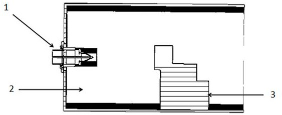
[0017] Such as figure 1 As shown in the structural diagram of the present invention, the microwave circular waveguide excitation device is connected to the magnetron and the reaction chamber respectively, including an output antenna 1 for connecting the magnetron, an excitation chamber 2 for energy feeding; Metal conductor 3; the metal conductor 3 is arranged in the excitation chamber 2 near the end of the reaction chamber.

[0018] Further, the metal conductor 3 ...


PUM


Abstract

The invention relates to the field of microwave transmission, in particular to a microwave circular waveguide excitation device, and solves the problems of large structural size and low output efficiency due to the fact that a magnetron takes a rectangular waveguide as a resonant cavity and then is connected with a circular waveguide in the prior art. The device is respectively connected with a magnetron and a reaction cavity, and comprises an output antenna used for connecting the magnetron and an excitation cavity used for energy feed-in, a metal conductor used for collecting energy. The metal conductor is arranged at one end, close to the reaction cavity, in the excitation cavity. By arranging the output antenna capable of being connected with the magnetron and the reaction cavity, microwave energy is output in the excitation cavity, the structure is simple and small, integration of a magnetron system is facilitated, the microwave output efficiency is high, and the microwave outputis not prone to being affected by loads, and by arranging a chamfer structure, the tip effect is effectively prevented.

Description

technical field [0001] The invention relates to the field of microwave transmission, in particular to a microwave circular waveguide excitation device. Background technique [0002] As a kind of microwave power source, magnetron is widely used in the microwave industry due to its advantages of low price, high efficiency and high power-to-mass ratio. The microwave output structure of the magnetron adopts an antenna design, which requires the use of a larger waveguide output structure, especially in the case of a larger rectangular excitation cavity converted to a circular waveguide; the application range is narrow and can only be used with waveguide interfaces. In the imported equipment, its output efficiency is easily affected by the load connected to the waveguide, which will be greatly reduced, and the return loss will increase due to structural changes, which will affect the service life of the magnetron. Moreover, the structural size is large, which is not conducive to ...

Claims


Application Information

Patent Timeline
Patent Type & Authority Applications(China)
IPC IPC(8): H01J23/36H01J25/50
CPCH01J23/36H01J25/50
Inventor 董鹭
Owner 成都迈频汇能科技有限公司
Learn More