Elevator

A lift and lift shaft technology, applied in the field of improved hydraulic drive lifts, can solve the problems of high cost and increased cost, and achieve the effect of increased flexibility

Inactive Publication Date: 2003-08-13
LOMAXMAIN
View PDF4 Cites 1 Cited by
  • Summary
  • Abstract
  • Description
  • Claims
  • Application Information

AI Technical Summary

Problems solved by technology

[0008] Another disadvantage of the lift structure described above is that the lift chamber is supported under static engineering conditions by a plunger
These devices are quite expensive and a slight increase in diameter increases their cost considerably

Method used


Image

  • Elevator
  • Elevator
  • Elevator

Examples


Embodiment Construction

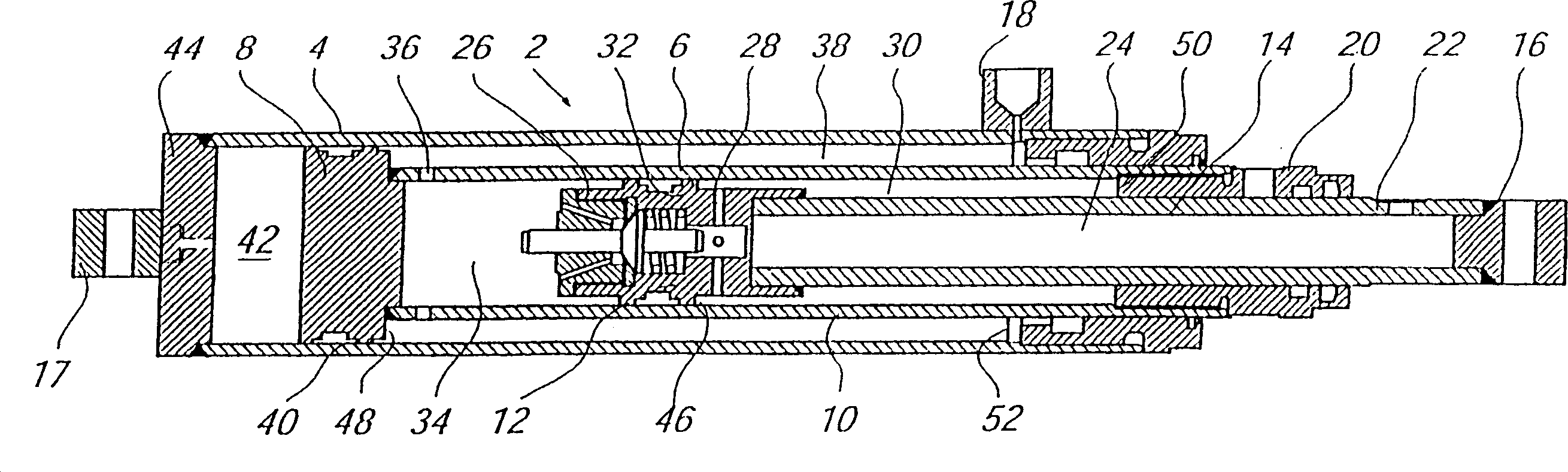
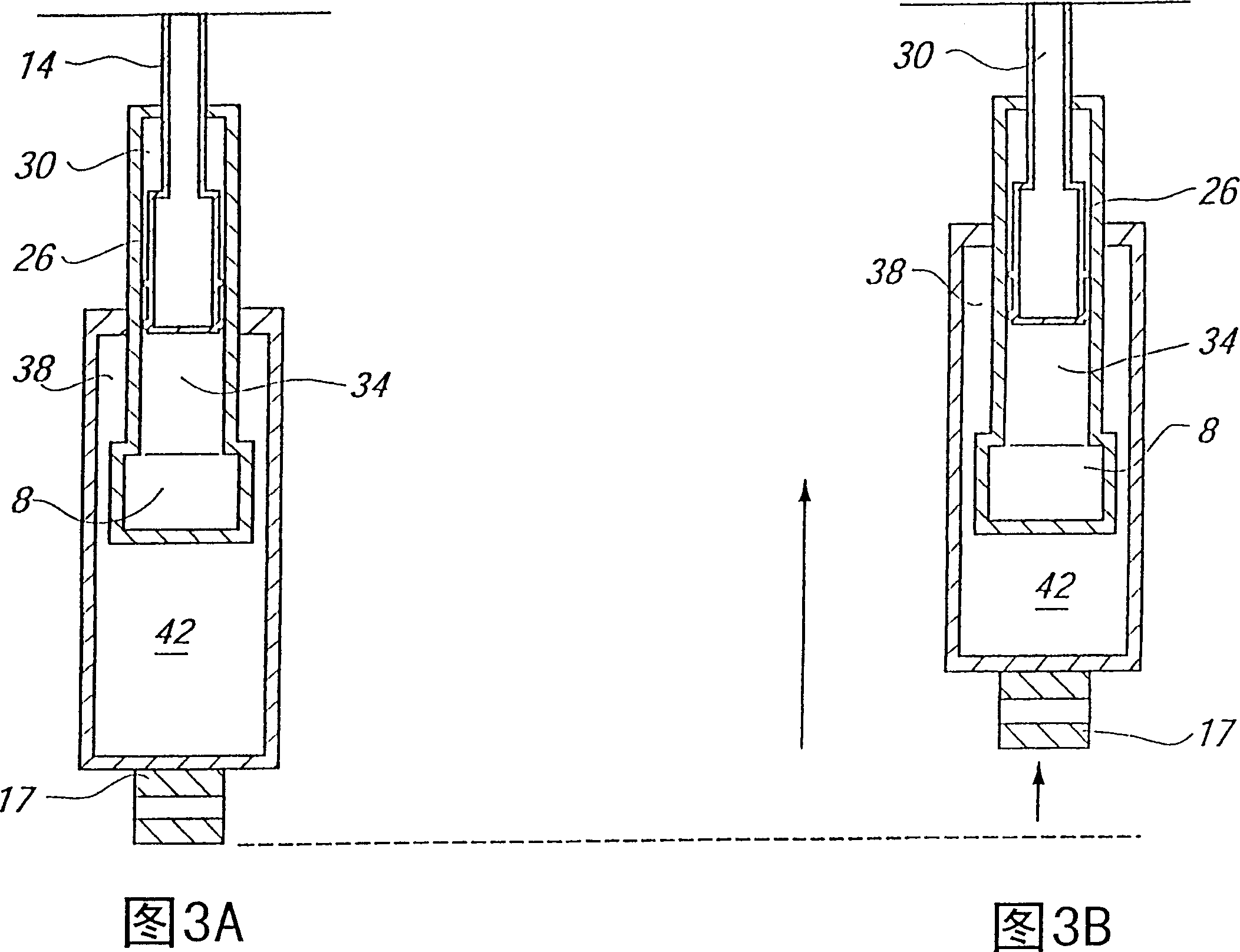
[0021] see first figure 1 , which shows a telescoping piston and cylinder assembly 2 with an outer cylinder 4 and an intermediate cylinder 6 having a piston head 8 and a cylinder 10, Cylinder 10 houses a piston head 12 mounted on an internal plunger 14 . An auxiliary device 16 is provided at one end of the inner plunger 14 through which a screw, pin or other similar member (not shown) can pass to secure the piston and cylinder assembly 2 in place in the elevator shaft superior. Another auxiliary device 17 is located on the base 44 of the external hydraulic cylinder to secure the external hydraulic cylinder to the elevator car. According to the invention, the above-mentioned position is located in the upper area of ​​the elevator shaft, from which the piston and hydraulic cylinder assembly 2 is suspended, as figure 2 shown.

[0022] Fluid inlets 18, 20 and 22 are provided on the outer hydraulic cylinder 4, cylinder body 10 and inner plunger 14, respectively, through which ...


PUM


Abstract

There is described an elevator construction comprising a cabin and a piston and cylinder arrangement attached thereto, the cabin being adapted to move within an elevator shaft. The piston of the arrangement is attached in the uppermost region of the shaft depends from its attachment which supports the entire arrangement and also the cabin, which is attached to the outer cylinder of the arrangement in the lowermost region thereof. The piston and cylinder arrangement may be telescopic in that a plurality of concentric pistons and cylinders may be disposed concentrically of one another, and respective hydraulic cavities thereof may be valved together so that the extension and contraction of the entire arrangement is smooth when hydraulic fluid is introduced thereinto or allowed to escape therefrom. The arrangement is such that the introduction of hydraulic fluid thereinto causes relative axial movement of respective and adjacent piston and cylinder components and an overall contraction of the arrangement. The cabin thus rises within the elevator shaft. The invention provides much greater control over elevator movement, and precludes the design emphasis on strut buckling, necessary in prior art designs in which the arrangement was mounted beneath the cabin and thus supported same in compression.

Description

technical field [0001] The present invention relates to an improved elevator, in particular to an elevator dedicated to an indoor environment or an environment where the length of the elevator shaft does not exceed a few floors and the carrying capacity is limited to a few people, most of these elevators are driven by hydraulic pressure , and the present invention generally relates to an improved hydraulically driven lift. Background technique [0002] Although the following description relates almost exclusively to indoor lifts, it will be apparent that the lift of the present invention can also be used in other than domestic environments. Furthermore, the range of application of the components of the present invention can also be extended so that the elevator can be used in other environments. [0003] At present, the drive of most indoor elevators is realized by hydraulic drive. The elevator chamber is fixed on the upper free end of a plunger which is located in a hydra...

Claims


Application Information

Patent Timeline
Patent Type & Authority Patents(China)
IPC IPC(8): B66B9/04
CPCB66B9/04
Inventor 伦纳德·伊登布鲁斯·伊登凯文·安斯利保罗·布里顿
Owner LOMAXMAIN
Why Eureka
Try Eureka