

Automatic shell breaking equipment for cooked eggs
A technology for cooked eggs and broken shells, which is applied in the field of equipment for automatic broken shells of cooked eggs, can solve the problems of inability to peel multiple eggs, and the efficiency of egg peeling is reduced, and achieves the effect of improving efficiency.
- Summary
- Abstract
- Description
- Claims
- Application Information
AI Technical Summary
Problems solved by technology
Method used
Image

Examples
Embodiment 1
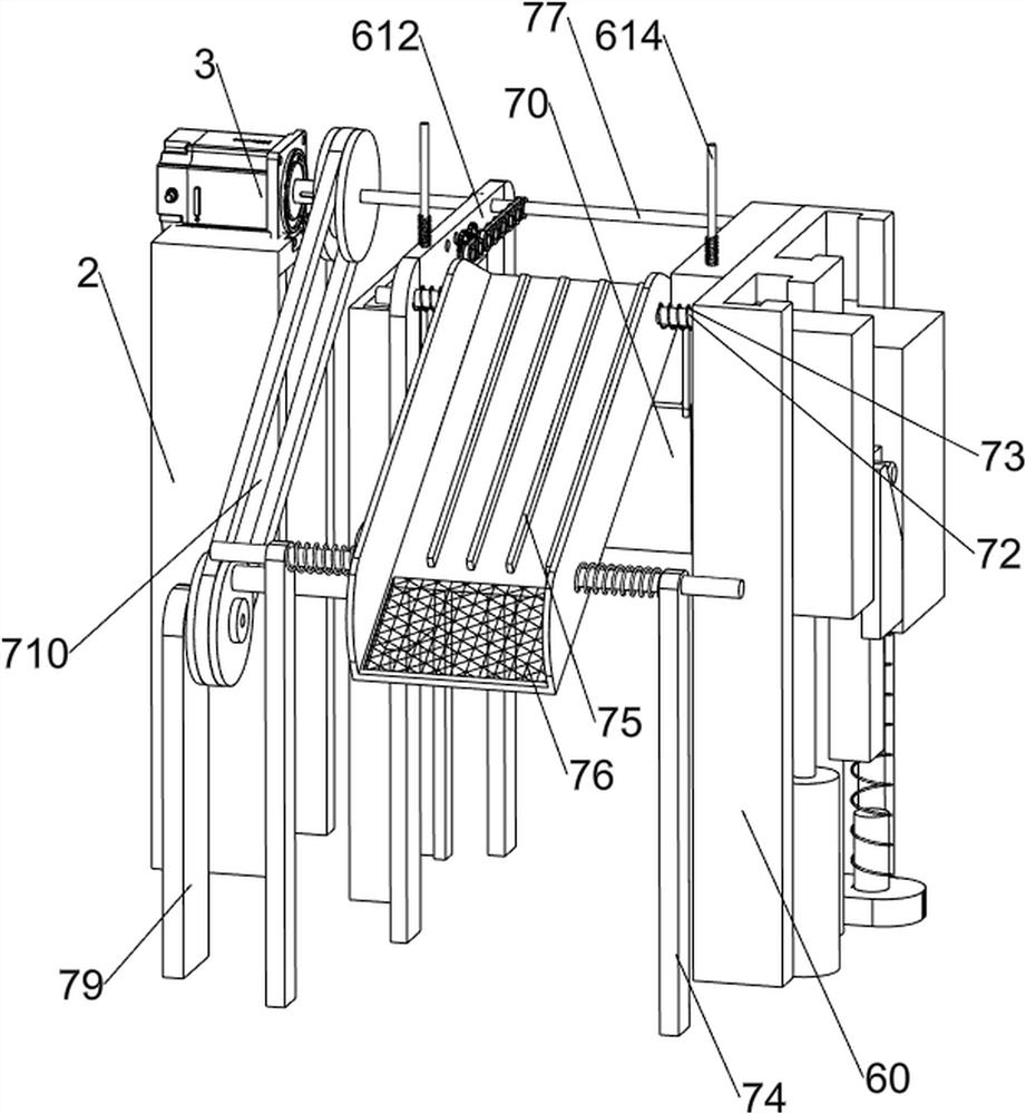
[0024] A kind of equipment for automatic boiled egg cracking, such as figure 1 As shown, it includes a base 1, a first support frame 2, a servo motor 3, a water storage basket 4, a first storage basket 5, a crushing mechanism 6, a blanking mechanism 7, a fourth support frame 8, a conveyor belt 9, a first The four pulley assembly 10 and the discharge chute 11, the first support frame 2 is arranged in the middle of the upper rear side of the base 1, the servo motor 3 is arranged on the upper part of the first support frame 2, the water storage basket 4 is arranged on the left side of the upper part of the base 1, and the water storage The first storage basket 5 is slidingly provided in the basket 4, the upper left side of the base 1 is provided with a shell crushing mechanism 6, the upper left side of the base 1 is provided with a feeding mechanism 7, and the upper right side of the base 1 is evenly provided with four fourth Bracing frame 8, the fourth supporting frame 8 between...
Embodiment 2
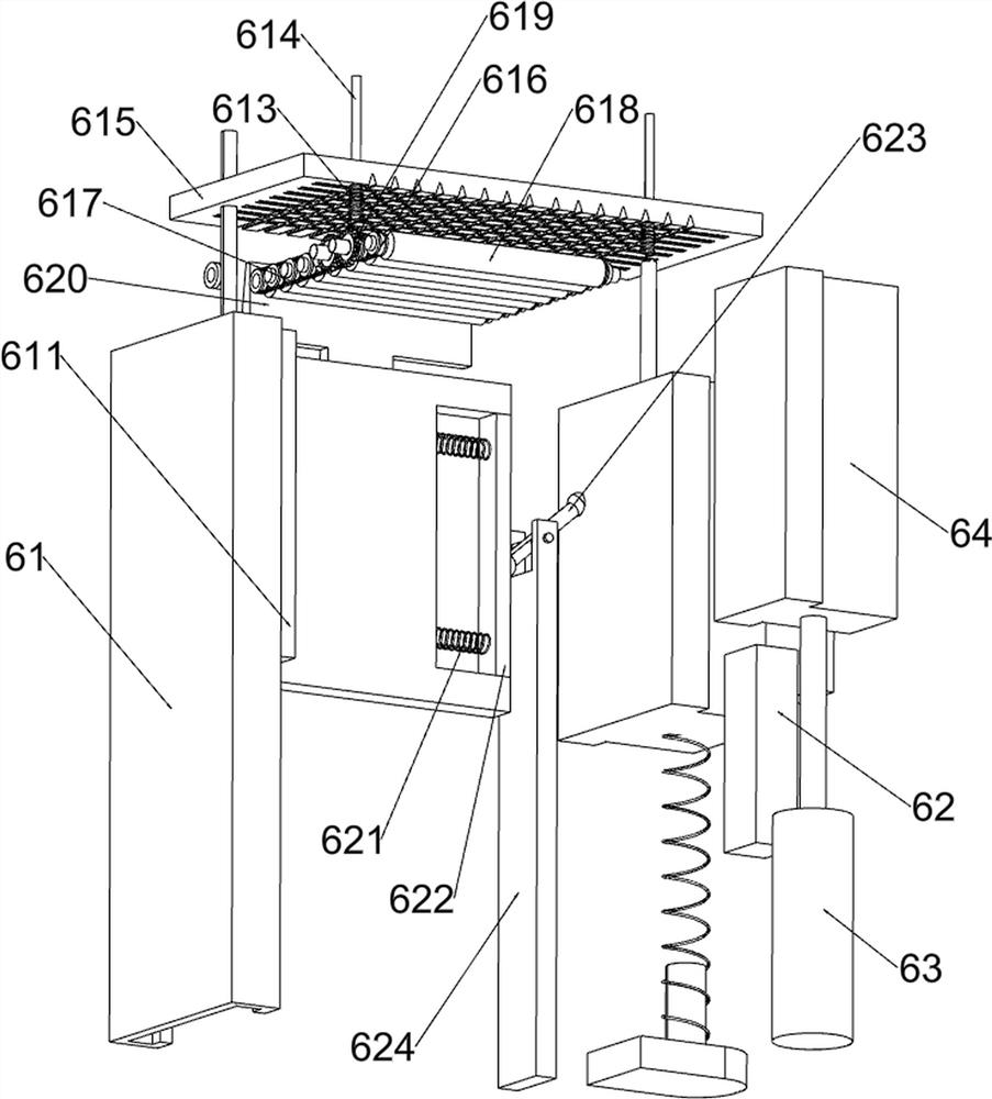
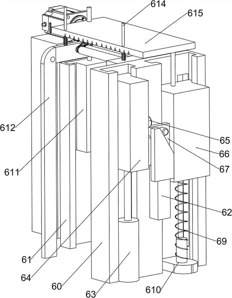
[0027] On the basis of Example 1, such as Figure 2-7As shown, the crushing shell mechanism 6 includes a first slide rail 60, a second slide rail 61, a connecting block 62, a cylinder 63, a first lifting member 64, a pushing block 65, a second lifting member 66, a telescopic clamping block 67, a A spring 68, a second spring 69, a fixed seat 610, a third slide block 611, a first support plate 612, a third spring 613, a guide rod 614, a lifting plate 615, a first pulley assembly 616, a second pulley assembly 617, Roller 618, full gear 619, baffle plate 620, the 5th spring 621, slide block 622, turning bar 623 and support 624, base 1 top front side middle is provided with the first slide rail 60, base 1 top rear side middle is provided with the first Two slide rails 61, a connection block 62 is provided in the middle of the front part of the first slide rail 60, a cylinder 63 is provided in the middle of the front side of the base 1 top, and a first lifter 64 is provided on the t...
Embodiment 3
[0032] On the basis of Example 2, such as figure 1 As shown, a protective plate 12 is also included, and the protective plate 12 is connected between the fourth support frames 8 on the left and right sides, and the protective plates 12 on the front and rear sides are respectively located on both sides of the conveyor belt 9 .
[0033] Because the egg is elliptical, the egg will deviate to the outside during the moving process, and the protective plates 12 on both sides can prevent the egg from falling to the outside during the moving process.
PUM
 Abstract
Description
Claims
Application Information