Detachable handle structure of water machine

A handle and water machine technology, applied in the installation of handles, electrical equipment, cleaning equipment, etc., can solve the problems of increasing the difficulty of operation, increasing labor intensity, not having electronic control devices, etc., reducing labor intensity, simplifying operation, and safety. Reliable effect

Pending Publication Date: 2020-10-16
NINGBO DECHANG ELECTRICAL MACHINERY MFG CO LTD
View PDF0 Cites 0 Cited by
  • Summary
  • Abstract
  • Description
  • Claims
  • Application Information

AI Technical Summary

Problems solved by technology

[0003] The existing vacuum cleaner handle is often only a single mechanical mechanism, and the handle is often not equipped with an electric control device. The electric control device is often arranged on the main body of the vacuum cleaner, so the operator often needs to bend over to operate the vacuum cleaner when using it. The use of this design not only increases the difficulty of operation, but also increases the labor intensity

Method used


Image

  • Detachable handle structure of water machine
  • Detachable handle structure of water machine
  • Detachable handle structure of water machine

Examples


Embodiment Construction

[0023] The present invention will be further described below in conjunction with the drawings and specific embodiments.

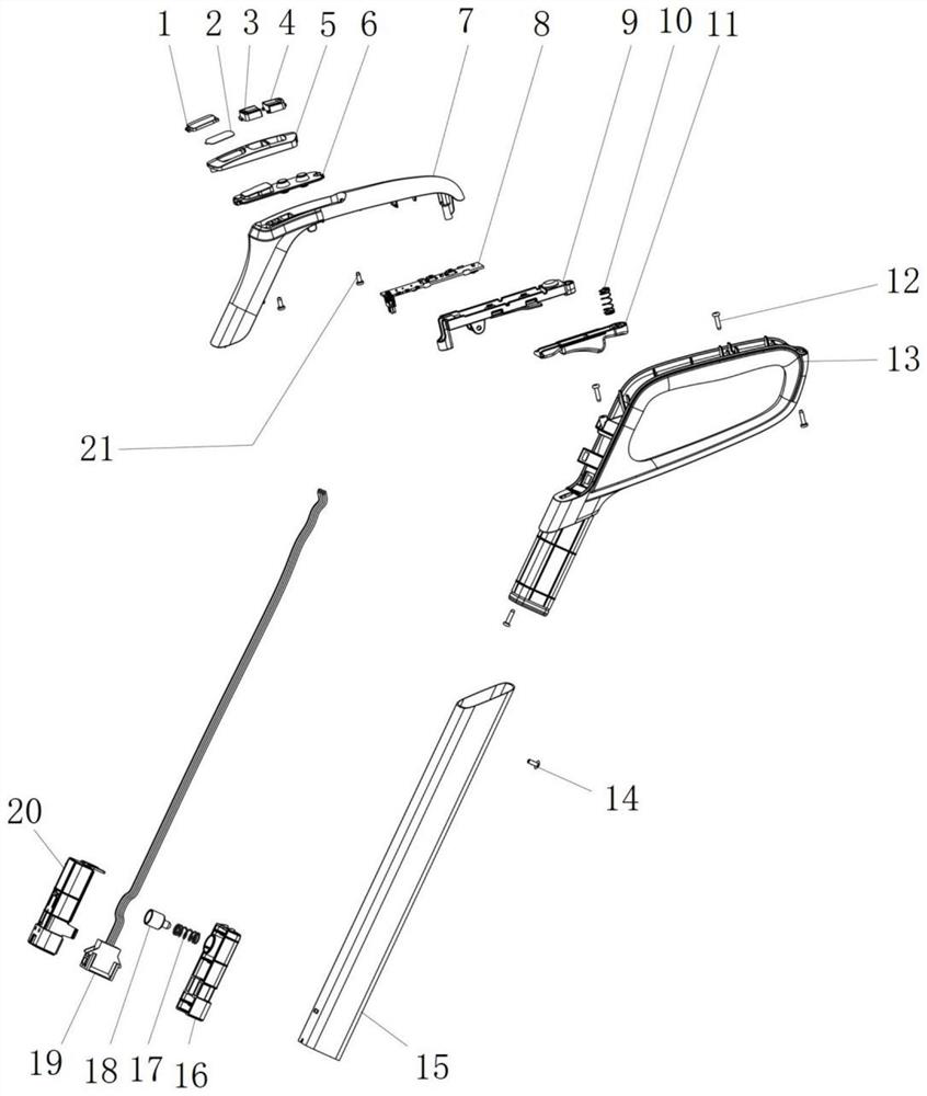
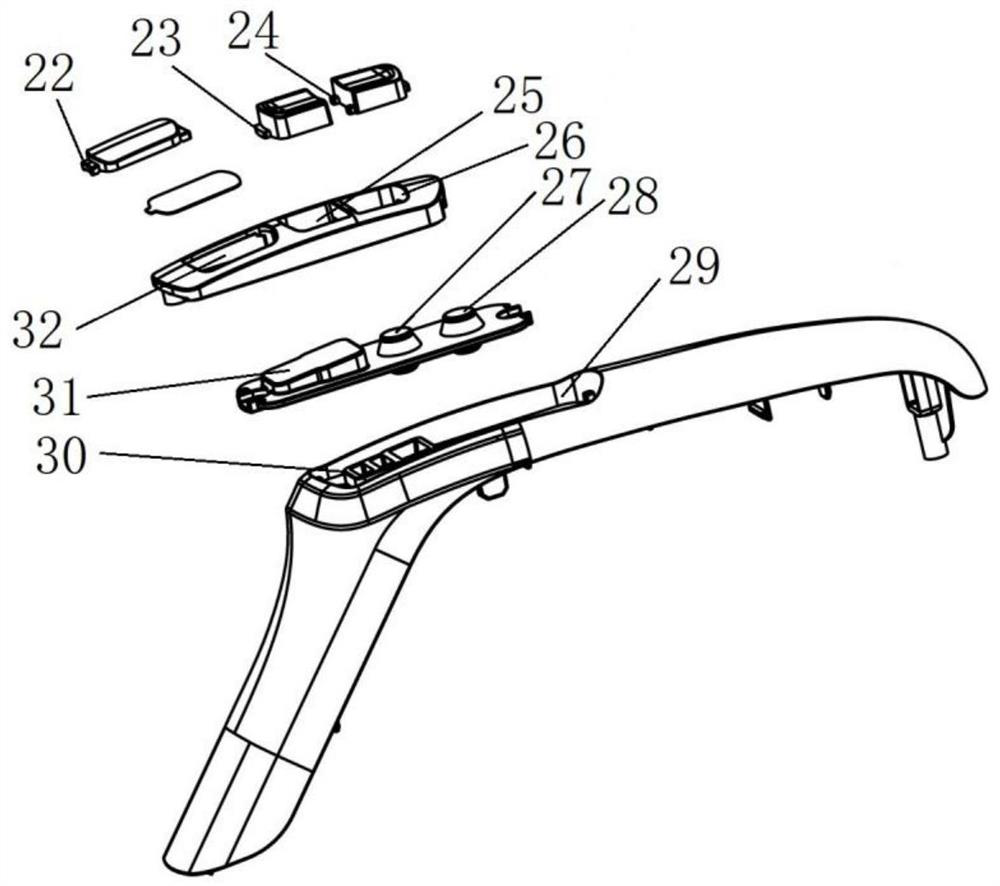
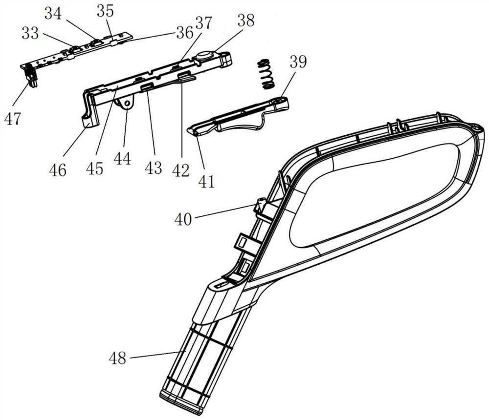
[0024] Such as figure 1 In the described embodiment, a detachable handle structure for a water machine includes a handle body 13, a handle upper cover 7, a button assembly, a circuit board assembly and a square tube assembly. The circuit board assembly is installed on the handle body 13 and placed on the handle. Between the body 13 and the upper handle cover 7, the button assembly is installed on the upper handle cover 7 and connected to the circuit board assembly. The square tube assembly includes a square tube body 15 and a plug assembly. The plug assembly is installed at the lower end of the square tube body 15. The upper end of the pipe body 15 is mounted on the handle body 13, and the plug assembly is electrically connected with the circuit board assembly. The lower end of the handle body 13 is provided with a plug 48, and the square tube body 15 is inser...


PUM


Abstract

The invention discloses a detachable handle structure of a water machine. The detachable handle structure comprises a handle body, a handle upper cover, a button assembly, a circuit board assembly anda square tube assembly, wherein the circuit board assembly is installed on the handle body and arranged between the handle body and the handle upper cover. The button assembly is installed on the handle upper cover and connected with the circuit board assembly, the square tube assembly comprises a square tube body and a plug assembly, the plug assembly is installed at the lower end of the squaretube body, the upper end of the square tube body is installed on the handle body, and the plug assembly is electrically connected with the circuit board assembly. The beneficial effects are that the operation of the dust collector is directly controlled through the button assembly on the handle upper cover, so that the operation is greatly simplified, and the labor intensity is reduced; the cutting operation of the dust collector body is realized by directly plugging and unplugging, so that the safety, reliability and stability of the whole dust collector are improved; and sealing performanceis good, safety and reliability are high, stability is good, and dismounting and mounting are convenient.

Description

Technical field [0001] The invention relates to the related technical field of vacuum cleaners, in particular to a detachable handle structure of a water machine. Background technique [0002] Vacuum cleaners can be divided into vertical, horizontal and portable according to their structure. The working principle of the vacuum cleaner is to use a motor to drive the blades to rotate at a high speed to generate negative air pressure in the sealed casing to absorb dust. Vacuum cleaners are mainly composed of three parts: dust collection, dust collection, and dust filtering, generally including series commutator motors, centrifugal fans, dust filters (bags) and dust collection accessories. The power of a general vacuum cleaner is 400-1000W or higher, and the power of a portable vacuum cleaner is generally 250W or less. The vacuum cleaner can remove dust mainly because its "head" is equipped with an electric exhaust fan. There is a wind impeller on the shaft of the exhaust fan. Aft...

Claims


Application Information

Patent Timeline
IPC IPC(8): A47L9/32A47L9/00A47L9/28
CPCA47L9/32A47L9/00A47L9/28A47L9/2857A47L9/2868
Inventor 张罗欢
Owner NINGBO DECHANG ELECTRICAL MACHINERY MFG CO LTD
Why Eureka
Try Eureka