Pulmonary artery stent convenient to control, and pulmonary artery valve replacement device

A valve replacement and pulmonary artery technology, applied in the direction of heart valve, valve annulus, etc., can solve the problem that the rotation direction of the contraction unit cannot be accurately controlled, patient injury, contraction direction deviation, etc., to achieve stable and reliable rotation direction, avoid injury, and rotate direction stable effect

Active Publication Date: 2020-10-16
SICHUAN UNIV
View PDF13 Cites 0 Cited by
  • Summary
  • Abstract
  • Description
  • Claims
  • Application Information

AI Technical Summary

Problems solved by technology

[0004] The pulmonary artery stent disclosed in the prior art has contractility, and the contraction units are diamond-shaped. The relative rotation between the contraction units can be controlled by using the connection points between the contraction units, but the rotation direction of the contraction units cannot be precisely controlled. During the process, it is easy to cause deviation in the contraction direction and cause injury to the patient.

Method used


Image

  • Pulmonary artery stent convenient to control, and pulmonary artery valve replacement device
  • Pulmonary artery stent convenient to control, and pulmonary artery valve replacement device
  • Pulmonary artery stent convenient to control, and pulmonary artery valve replacement device

Examples


Embodiment

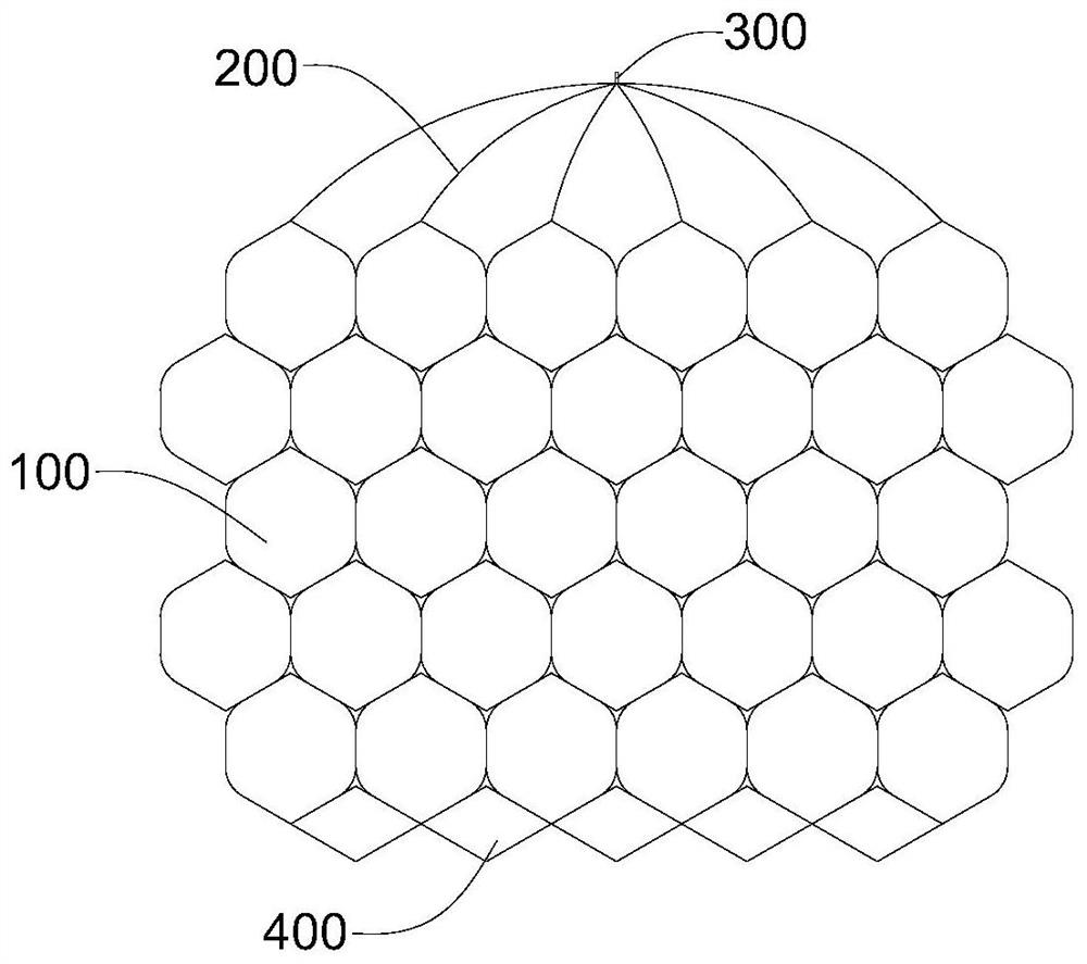
[0051] refer to Figure 1 to Figure 5 , the embodiment of the present invention discloses a controllable pulmonary artery stent, which includes a tubular support grid 100 , a fixing member 300 , an outflow stent 400 and at least two groups of aortic stents 200 .

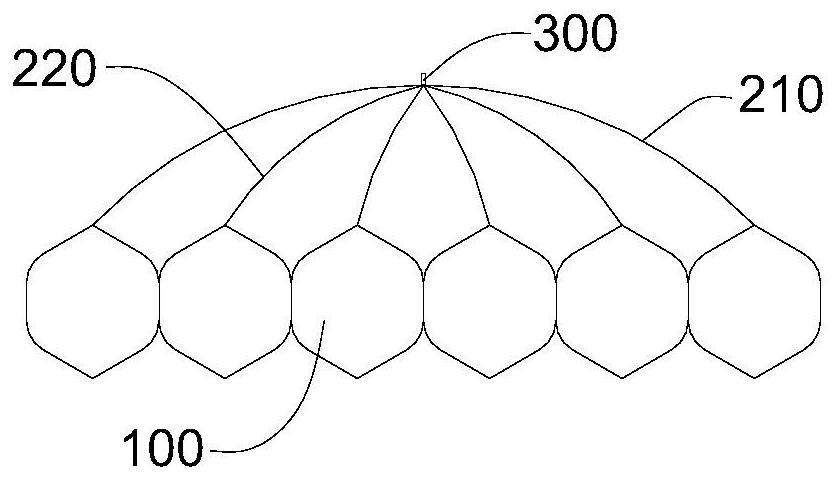
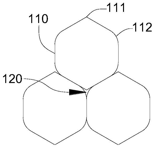
[0052] The supporting grid 100 is composed of continuous rotating units 110, adjacent rotating units 110 are connected in rotation, the rotating units 110 are in the shape of a regular hexagonal frame, and the vertices of the rotating units 110 located at both ends of the supporting grid 100 are connection points 111; the aortic stent 200 includes a support bar 210 and four auxiliary bars 220, every six connection points 111 are a group, the two ends of the support bar 210 are respectively connected to the two farthest connection points 111, and the four auxiliary bars 220 are connected to the middle The four connection points 111 are connected in one-to-one correspondence, the end of the auxiliary bar 220 away from ...


PUM


Abstract

The invention discloses a pulmonary artery stent convenient to control. The pulmonary artery stent convenient to control comprises a tubular supporting net frame, fixing pieces, a flowing out stent and at least two groups of aorta stents, wherein the supporting net frame consists of continuous regular hexagon rotating units, and top points located at two ends of the supporting net frame, of the rotating units are connecting points; each aorta stent comprises a supporting strip and four auxiliary strips, two ends of each supporting strip are respectively connected with two connecting points which are the farthest from each other, the four auxiliary strips are connected with four connecting points in the middle in a one-to-one correspondence, one end departing from the connecting points, ofeach auxiliary strip and the corresponding supporting strip are connected to one point, and the corresponding fixing piece is located at the connecting position of each supporting strip and the corresponding auxiliary strip; and the flowing out stent is located at the other end of the supporting net frame. According to the pulmonary artery stent convenient to control disclosed by the invention, the connecting lines between rotating units in the pulmonary artery stent convenient to control are long, every two adjacent rotating units rotate along the corresponding connecting line, during rotation, the rotation direction is stable and reliable, and accidental situations appearing in a mounting process can be effectively avoided and reduced.

Description

technical field [0001] The present application relates to the field of medical devices, in particular, to a controllable pulmonary artery stent and a pulmonary valve replacement device. Background technique [0002] Pulmonary valve stenosis usually refers to pulmonary valve or pulmonary valve combined with right ventricular outflow tract stenosis. It can exist alone or be one of the lesions of other complex congenital heart diseases (such as tetralogy of Fallot). Pulmonary stenosis The incidence rate accounts for 10% to 20% of the total number of congenital heart diseases. According to the different parts of the stenosis, it can be divided into pulmonary valve stenosis, funnel stenosis, and main pulmonary artery and pulmonary artery branch stenosis, among which pulmonary valve stenosis is the most common. The surgical method for pulmonary artery stenosis should be determined according to different lesions. At present, the operation for treating waste aortic valve is mainly...

Claims


Application Information

Patent Timeline
Patent Type & Authority Applications(China)
IPC IPC(8): A61F2/24
CPCA61F2/2418A61F2/2442A61F2/2463
Inventor 王云兵蔡伊凡雷洋杨立陈宇熊艳
Owner SICHUAN UNIV
Why Eureka
Try Eureka