

Liquid separator
A technology of liquid separator and liquid separation tank, which is applied in the direction of separation methods, filtration separation, chemical instruments and methods, etc., and can solve the problem of affecting the liquid separation quality and service life of the liquid separation tank, the inability to know the liquid level of the liquid separation tank, and solid impurities Access and other issues, to achieve good use value, convenient observation, to ensure the effect of normal use
- Summary
- Abstract
- Description
- Claims
- Application Information
AI Technical Summary
Problems solved by technology
Method used
Image

Examples
Embodiment 1
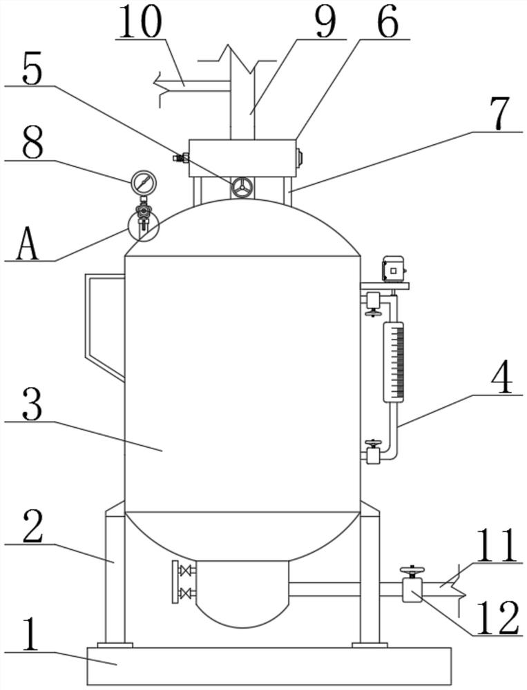
[0027] see figure 1 , figure 2 , image 3 , Figure 4 , Figure 5 with Image 6 , the present invention provides a technical solution:
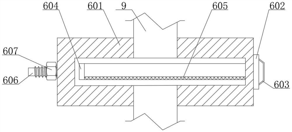
[0028] The liquid separator includes a base 1 and a supporting leg 2. The upper end of the base 1 is fixedly connected with supporting legs 2 distributed left and right. Feeding pipe 9, feeding pipe 9 guarantees the normal feeding of materials, and the outer side of feeding pipe 9 is fixedly connected with filtering device 6, and filtering device 6 comprises filtering frame 601 and sealing plate 602, and the upper and lower ends of filtering frame 601 are connected with feeding pipe 9 Connected, the inside of the filter frame 601 is slidably connected with a sliding frame 604, the lower end of the sliding frame 604 is fixedly connected with a screen 605, the right end of the sliding frame 604 is fixedly connected with a sealing plate 602, and the right end of the sealing plate 602 is fixedly connected with a handle 603, the handle 603 ...
Embodiment 2
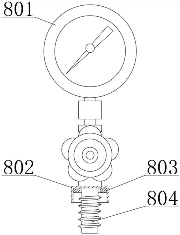
[0031] In Embodiment 2, the same parts as Embodiment 1 will not be repeated, the difference is that when the pressure sensor 801 is damaged and needs to be replaced or needs to be cleaned, by turning the rotating plate 805 to the front side, and then rotating the limit frame 802 , the limit frame 802 drives the hollow connecting rod 804 to rotate, so as to realize the separation from the connecting pipe 806, facilitate the replacement or cleaning of the pressure sensor 801, and ensure the normal use of the equipment.
PUM
 Abstract
Description
Claims
Application Information