Industrial waste gas treatment device

A technology for treatment devices and industrial waste gas, which is applied in the directions of dispersed particle separation, direct contact heat exchangers, chemical instruments and methods, etc. Air pollution, the effect of reducing workload

Active Publication Date: 2020-10-16
HENAN INST OF SCI & TECH
View PDF15 Cites 1 Cited by
  • Summary
  • Abstract
  • Description
  • Claims
  • Application Information

AI Technical Summary

Problems solved by technology

[0002] With the development of society, the rapid development of industry has brought great convenience to people's life, but industry has also brought serious environmental problems. Usually, industrial waste gas needs to be treated before being discharged into the atmosphere. Existing The waste gas treatment device directly treats the waste gas. However, when many industrial waste gases are discharged, the temperature is very high, which will cause serious damage to the treatment device and the treatment effect is poor. Some waste gas treatment devices will spray water when treating high-temperature waste gas. , but it cannot be adjusted according to the amount of waste gas treatment. Too much water spraying will cause waste, and too little water spraying will not achieve the effect. Therefore, it is necessary to improve the existing waste gas treatment device

Method used


Image

  • Industrial waste gas treatment device
  • Industrial waste gas treatment device
  • Industrial waste gas treatment device

Examples


Embodiment Construction

[0020] The present invention will be further described in detail below in conjunction with the accompanying drawings and examples. The following examples are explanations of the present invention and the present invention is not limited to the following examples.

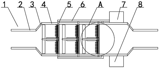
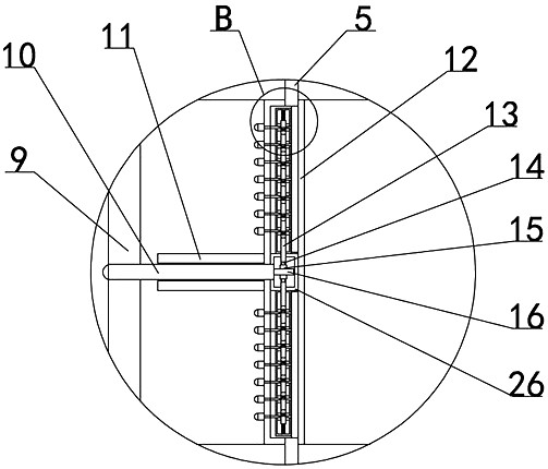
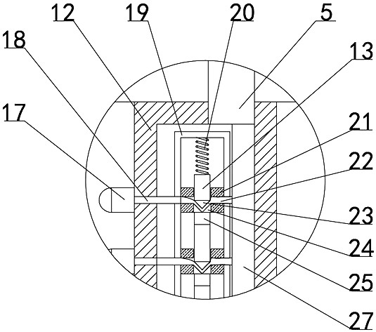
[0021] like Figure 1-6 As shown, an industrial waste gas treatment device includes a device body 1, the left side of the device body 1 is connected to the intake pipe 2, the right side of the intake pipe 2 is connected to the expansion pipe 3, the right side of the expansion pipe 3 is connected to the processing cylinder 4, and the upper side of the processing cylinder 4 The water tank 7 is fixed, the waste water tank 8 is fixed on the lower side of the treatment cylinder 4, three sets of blades 9 are arranged in the treatment cylinder 4, the middle part of each set of blades 9 is fixed on the first rotating shaft 10, and the right part of the first rotating shaft 10 is rotated and arranged in the casing 11 , the s...


PUM


Abstract

The invention relates to the technical field of industrial waste gas treatment, and particularly relates to an industrial waste gas treatment device comprising a device body, an air inlet pipe is connected to the left side of the device body; an expansion tube is connected to the right side of the air inlet pipe; a treatment cylinder is connected to the right side of the expansion pipe; a water tank is fixed on the treatment cylinder; a wastewater tank is fixed below the treatment cylinder; three groups of blades are arranged in the treatment cylinder; the middle of each group of blades is fixed on the first rotating shaft; the right part of the first rotating shaft is rotationally arranged in the sleeve; the sleeve is fixed on the first fixed box; a second rotating shaft is fixed at the right end of the first rotating shaft; a connecting plate is circumferentially fixed on the outer side of the second rotating shaft; a first wedge block is fixed on the outer side of the connecting plate; a spray head is arranged on the left side plate of first fixed box; when high-temperature waste gas enters the treatment barrel through the air inlet pipe, the blades are driven to rotate, the blades rotate to enable the spray head to spray water and cool the waste gas, meanwhile, particles in the waste gas are removed, loss of the high-temperature waste gas to the treatment device is reduced,the water amount sprayed out of the spray head can be controlled through rotation of the blades, and water resources are saved.

Description

technical field [0001] The invention relates to the technical field of industrial waste gas treatment, in particular to an industrial waste gas treatment device. Background technique [0002] With the development of society, the rapid development of industry has brought great convenience to people's life, but industry has also brought serious environmental problems. Usually, industrial waste gas needs to be treated before being discharged into the atmosphere. Existing The waste gas treatment device directly treats the waste gas. However, when many industrial waste gases are discharged, the temperature is very high, which will cause serious damage to the treatment device and the treatment effect is poor. Some waste gas treatment devices will spray water when treating high-temperature waste gas. , but it cannot be adjusted according to the amount of waste gas treatment. Too much water spraying will cause waste, and too little water spraying will not achieve the effect. Therefo...

Claims


Application Information

Patent Timeline
Patent Type & Authority Applications(China)
IPC IPC(8): B01D47/06F28C3/06
CPCB01D47/06F28C3/06
Inventor 周凌云杜玉良王素芬
Owner HENAN INST OF SCI & TECH
Why Eureka
Try Eureka