A Forming Technology of Slender Hydraulic Tool Holder

A forming process, slender technology, applied in the field of forming process of hydraulic tool holder, can solve the problems such as welding reliability cannot be effectively guaranteed, affect the final forming quality of hydraulic tool holder, and the connection cannot be flawless, etc., and achieve reliable assembly. , convenient parameter control, easy to use effect

Active Publication Date: 2021-12-24
XIANGSHAN METALLURGICAL & MINING MACHINERY & EQUIP
View PDF5 Cites 0 Cited by
  • Summary
  • Abstract
  • Description
  • Claims
  • Application Information

AI Technical Summary

Problems solved by technology

[0004] However, the handle body, the fixed head and the expansion sleeve are fixed by welding, and there must be a weld between the two
On the one hand, the existence of welds affects the appearance of the hydraulic tool holder; on the other hand, the reliability of welding cannot be effectively guaranteed, and there is a possibility of hydraulic oil leakage in the welds
In addition, due to the existence of machining errors, the butt connection between the tool holder body, the fixed head and the expansion sleeve cannot be perfect, and there are more or less tiny dislocations or gaps, which also affect the final forming quality of the hydraulic tool holder

Method used


Image

  • A Forming Technology of Slender Hydraulic Tool Holder
  • A Forming Technology of Slender Hydraulic Tool Holder
  • A Forming Technology of Slender Hydraulic Tool Holder

Examples


Embodiment Construction

[0052] The following description serves to disclose the present invention to enable those skilled in the art to carry out the present invention. The preferred embodiments described below are only examples, and those skilled in the art can devise other obvious variations.

[0053] In the description of the present invention, it should be noted that for orientation words, such as the term "center", "horizontal", "longitudinal", "length", "width", "thickness", "upper", "lower" , "Front", "Back", "Left", "Right", "Vertical", "Horizontal", "Top", "Bottom", "Inner", "Outer", "Clockwise", "Counterclockwise " and other indication orientations and positional relationships are based on the orientations or positional relationships shown in the drawings, and are only for the convenience of describing the present invention and simplifying the description, rather than indicating or implying that the device or element referred to must have a specific orientation, or in a specific orientation...


PUM


Abstract

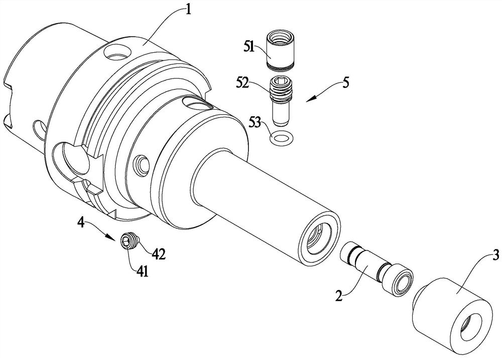
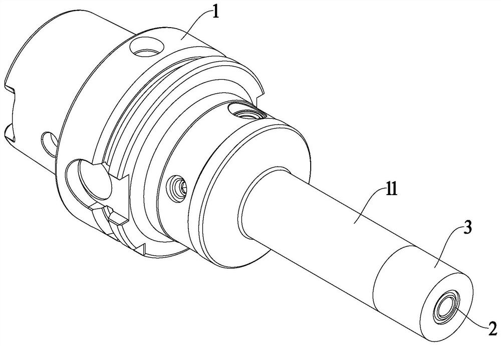
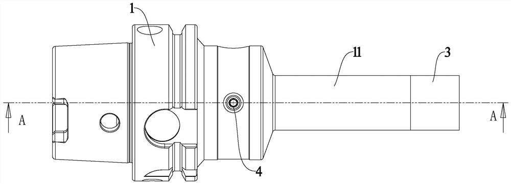
A molding process of a slender hydraulic tool handle according to the present invention is characterized in that it includes the following steps: S1: processing and forming the tool handle body, the expansion sleeve and the fixed head respectively; the front end of the tool handle body is processed and formed with a cylindrical extension There is an oil passage in the tool handle body; the fixed head is a cylindrical structure that can be smoothly connected with the extension column; S2: Weld the expansion sleeve and the fixed head on the extension column, and make the tool handle body, expansion sleeve and An oil chamber communicating with the oil passage is formed between the fixed heads; S3: Carry out cutting processing on the outer surfaces of the extension column, the expansion sleeve and the fixed head to form a tapered chuck. It has the advantages of low process difficulty, high molding quality, and the hydraulic tool holder has an integrated appearance.

Description

technical field [0001] The invention relates to the technical field of hydraulic tool holders, in particular to a forming process of hydraulic tool holders. Background technique [0002] Compared with various types of rigid tool holders such as spring sleeve type, shrink-fit type, side-fixed type, and tapered needle roller pressing type, hydraulic tool holders are flexible and fixed, and when the tool holder vibrates, the tool The damage can be greatly reduced, and it has been widely used in modern CNC machining equipment. [0003] Existing slender hydraulic tool handles generally include a tool handle body, an expansion sleeve, a fixed head, a pressure applying component, and an oil seal component. The expansion sleeve is welded and fixed on the conical extension column through the fixed head to form a conical chuck, and an oil cavity is formed between the conical extension column and the expansion sleeve, and an oil passage connecting the oil cavity is also opened in the ...

Claims


Application Information

Patent Timeline
Patent Type & Authority Patents(China)
IPC IPC(8): B23P15/28
CPCB23P15/28
Inventor 金青云
Owner XIANGSHAN METALLURGICAL & MINING MACHINERY & EQUIP
Why Eureka
Try Eureka