Sludge bin

A silo and sludge technology, applied to containers, packaging, underwater structures, etc., can solve the problems of dirty environment, water leakage, falls, etc., improve the installation environment, improve safety, and avoid blocking pollution mud effect

Inactive Publication Date: 2020-10-16
江苏沪一环保科技有限公司
View PDF0 Cites 1 Cited by
  • Summary
  • Abstract
  • Description
  • Claims
  • Application Information

AI Technical Summary

Problems solved by technology

[0003] Water leakage often occurs at the bottom of the existing sludge silo, and the seeped water drops on the ground, which will cause the site environment to be particularly dirty, chaotic, and poor.
And because the dripping water makes the ground slippery, it may also cause passing accidents to fall

Method used


Image

  • Sludge bin
  • Sludge bin
  • Sludge bin

Examples


Embodiment 1

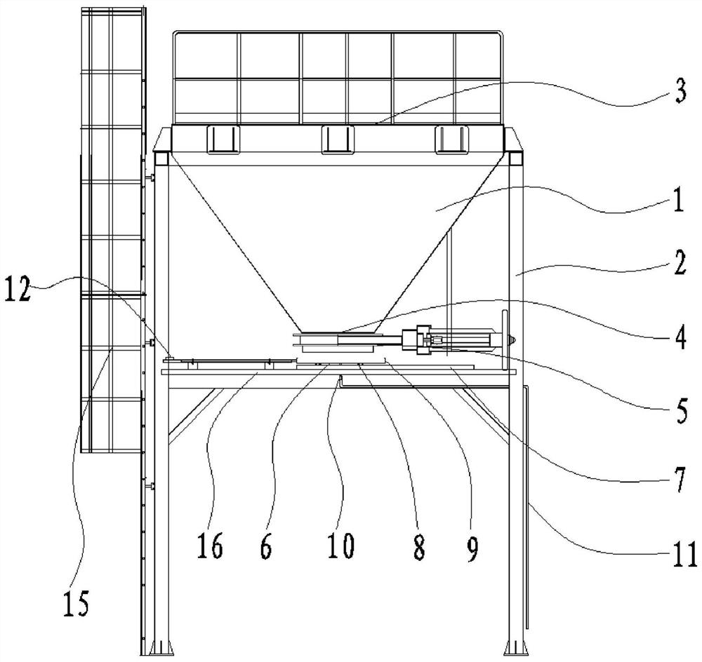
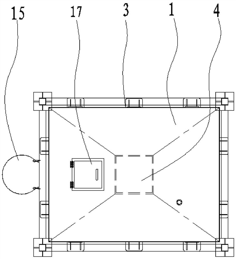
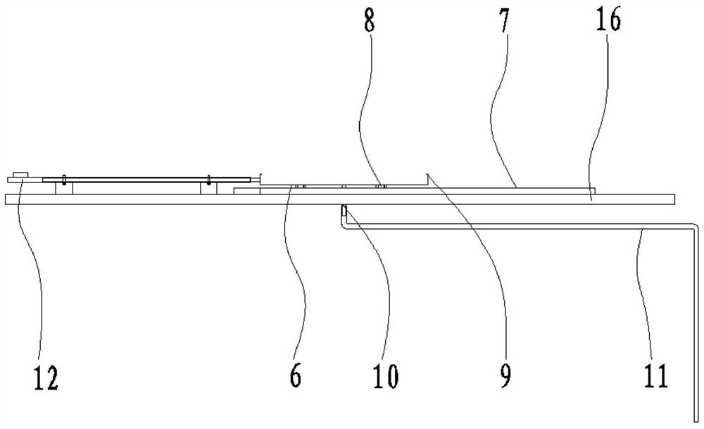
[0034] Such as Figure 1 to Figure 3 As shown, this embodiment includes a silo body 1 and a support frame 2 for supporting the silo body 1. In this embodiment, the silo body 1 is funnel-shaped, and the silo body 1 is set on the upper part of the support frame 2, the upper part of the silo body 1 is provided with a material inlet 3, the bottom of the silo body 1 is provided with a discharge port 4, and the discharge port 4 is provided with Discharge valve 5, the bottom of the discharge port 4 is provided with a water collection mechanism for collecting the leakage water of the discharge valve 5, and the water collection mechanism is connected to the leakage water collected by the water collection mechanism. The water is discharged from the drainage mechanism of the water collection mechanism, and the support frame 2 is provided with a device for driving the water collection mechanism to move to the vertical bottom of the discharge valve 5 and to leave the vertical bottom of the...

Embodiment 2

[0040] This embodiment includes a silo body 1 and a support frame 2 for supporting the silo body 1. In this embodiment, the silo body 1 is funnel-shaped, and the silo body 1 is located at The upper part of the support frame 2, the upper part of the silo body 1 is provided with a feed port 3, the bottom of the silo body 1 is provided with a discharge port 4, and the discharge port 4 is provided with a discharge valve 5. A water collection mechanism for collecting the leakage water of the discharge valve 5 is provided below the discharge port 4, and the water collection mechanism is connected to discharge the leakage water collected by the water collection mechanism into the The drainage mechanism of the water collection mechanism, the support frame 2 is provided with a driving mechanism for driving the water collection mechanism to move to the vertical bottom of the discharge valve 5 and to break away from the vertical bottom of the discharge valve 5 It should be noted that the...


PUM


Abstract

The invention relates to the technical field of sludge treatment equipment, in particular to a sludge bin. The sludge bin comprises a bin body and a supporting frame, wherein a feeding port is formedin the upper portion of the bin body, a discharging port is formed in the bottom portion of the bin body, an unloading valve is arranged at the discharging port, a water collecting mechanism used forcollecting leakage water of the unloading valve is arranged below the discharging port, the water collecting mechanism is connected with a water draining mechanism, and the supporting frame is provided with a driving mechanism used for driving the water collecting mechanism to move to the vertical lower portion of the unloading valve and disengage from the vertical lower portion of the unloading valve. The sludge bin has the beneficial effects that when sludge is not unloaded, the water collecting mechanism is moved to the vertical lower portion of the unloading valve to collect the leakage water at the bottom of the bin body, so that the leakage water is prevented from dropping to the ground, the mounting environment of the sludge bin is effectively improved, and the safety is improved; and when the sludge needs to be unloaded, the driving mechanism drives the water collecting mechanism to disengage from the vertical lower portion of the unloading valve, so that the water collecting mechanism is prevented from blocking the sludge, and the damage to the water collecting mechanism caused by sludge falling can be avoided.

Description

technical field [0001] The invention relates to the technical field of sludge treatment equipment, in particular to a sludge silo. Background technique [0002] In the sludge treatment process, the sludge dehydrated by the dehydrator needs to be transported and transferred out of the sewage treatment plant. It is usually stored in a silo and then transported by truck to the factory. The sludge silo is suitable for the storage, quantitative batching and transportation of high-humidity viscous substances such as dewatered sludge. It has the characteristics of continuous operation and adjustable transportation volume. [0003] Water leakage often occurs at the bottom of the existing sludge silo, and the seeped water drops on the ground, which will cause the site environment to be particularly dirty, chaotic and poor. And because the dripping water marks make the ground wet and slippery, it may also cause the passing personnel to have a falling accident. Contents of the inven...

Claims


Application Information

Patent Timeline
Patent Type & Authority Applications(China)
IPC IPC(8): B65D90/24B65D90/54B65D90/00B65D90/10B65D88/26
CPCB65D88/26B65D90/00B65D90/10B65D90/24B65D90/54
Inventor 许克楼高军陶辉高华潘永君
Owner 江苏沪一环保科技有限公司
Why Eureka
Try Eureka