Novel phase-change material filling device for electric heat storage building radiant floor heating

A phase change material and filling device technology, applied in electric heating systems, heating methods, heating systems, etc., can solve the problems of affecting filling efficiency, residual accumulation, affecting the service life of device transportation, etc., to improve filling efficiency, avoid accumulation, The effect of increasing efficiency

Active Publication Date: 2020-10-16
JILIN UNIV
View PDF10 Cites 0 Cited by
  • Summary
  • Abstract
  • Description
  • Claims
  • Application Information

AI Technical Summary

Problems solved by technology

[0004] Based on the fact that the anti-blocking cleaning device is not used in the conveying pipeline, the material will remain and accumulate in the conveying pipeline during the long-term use of the device, thereby affecting the filling efficiency and the conveying service life of the device. The present invention proposes A new phase change material filling device for building floor heating with electric heat storage

Method used


Image

  • Novel phase-change material filling device for electric heat storage building radiant floor heating
  • Novel phase-change material filling device for electric heat storage building radiant floor heating
  • Novel phase-change material filling device for electric heat storage building radiant floor heating

Examples


Embodiment 1

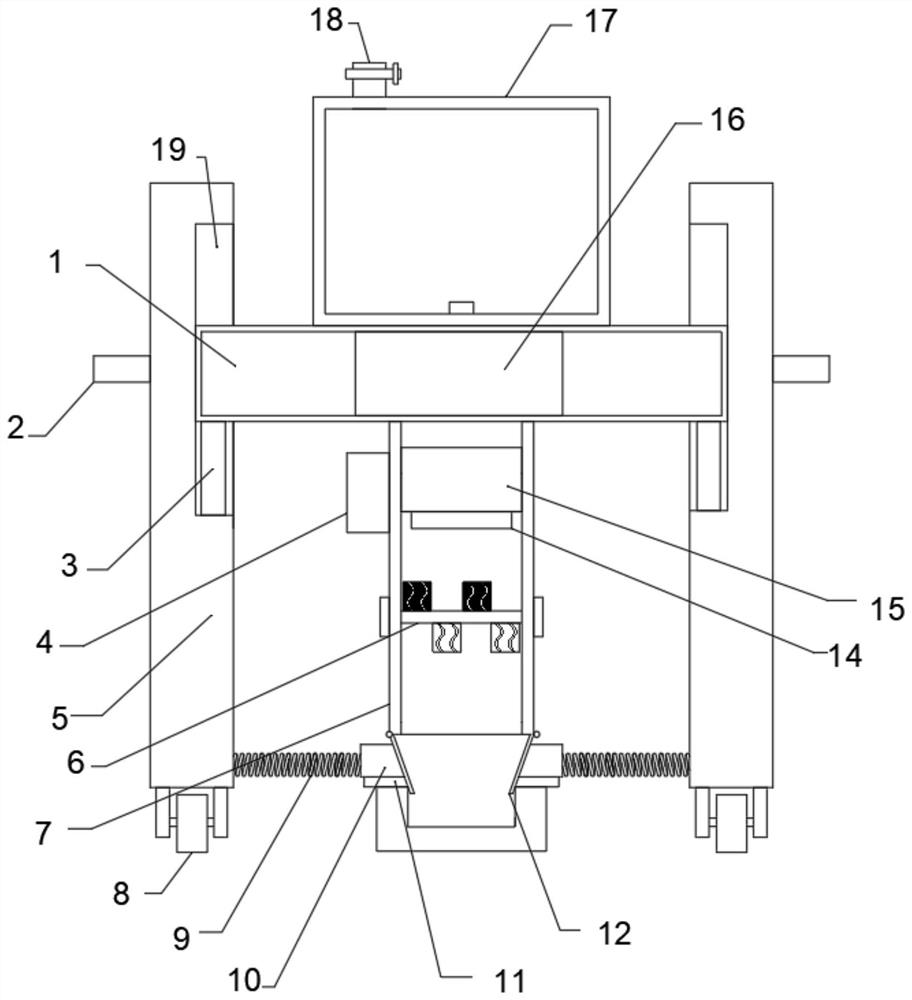
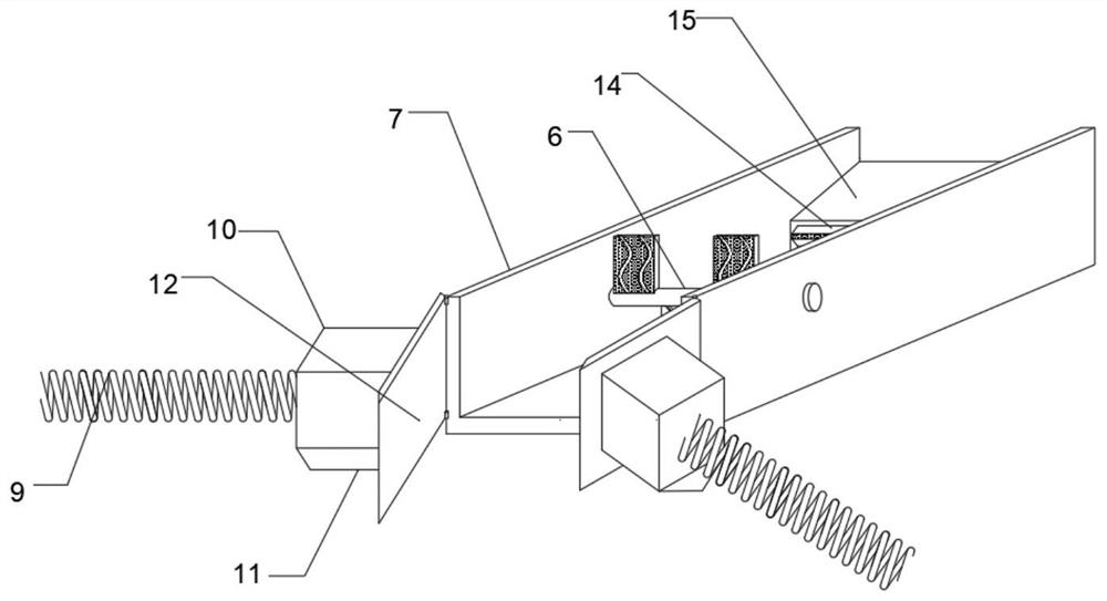
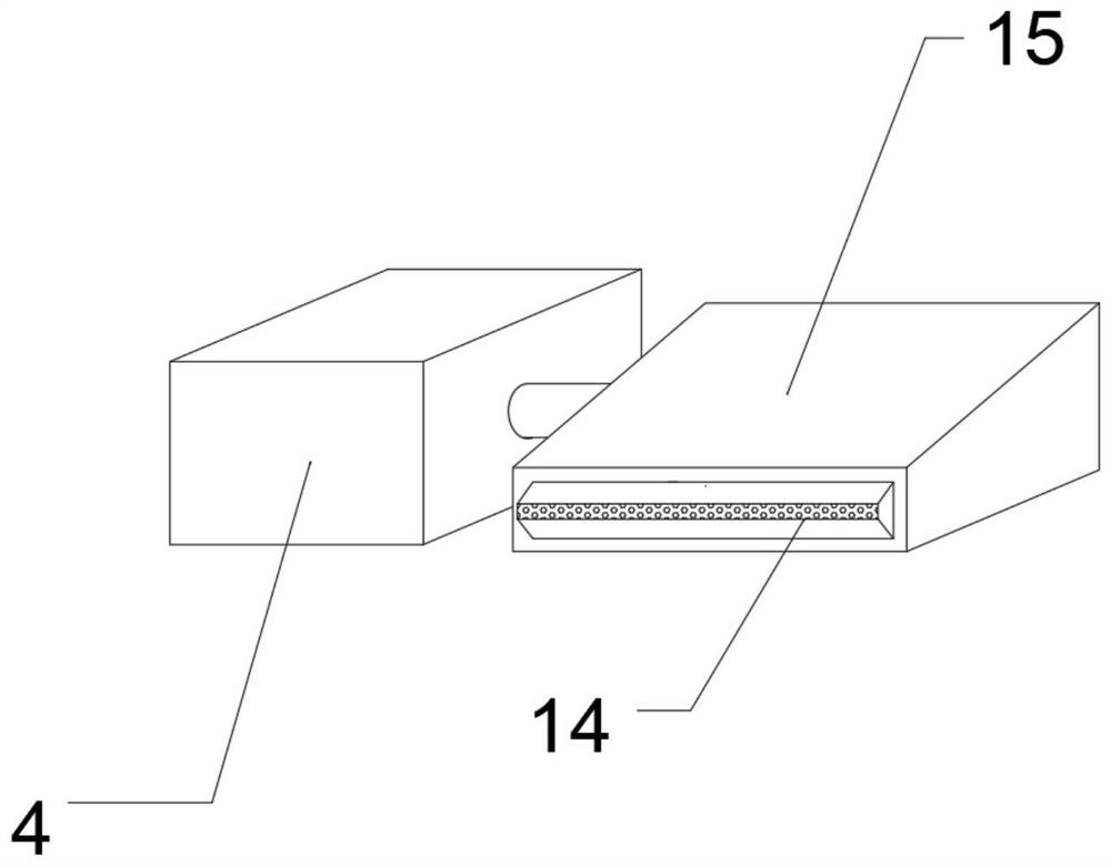
[0027] refer to Figure 1-4 , a new type of phase change material filling device for electric heat storage building floor heating, comprising a box body 1, a feeding mechanism is arranged on the top of the box body 1, a delivery pipeline 7 is fixedly connected to the outer wall of the bottom of the box body 1, and the outer wall of one end of the delivery pipeline 7 is fixedly connected There is an air pump 4, and the inner wall of the conveying pipeline 7 is fixedly connected with an air guide box 15, and the air guide box 15 is fixedly connected with the air pump 4. The air outlet pipe 14, the bottom of the air outlet pipe 14 is provided with a rotating mechanism, the rotating mechanism includes a first stopper 21 and a second stopper 22, the bottom of the air outlet pipe 14 is provided with a first rotating shaft 13, the first rotating shaft 13 and the conveying The pipeline 7 is connected in rotation, the top outer wall of the first rotating shaft 13 is fixedly connected w...

Embodiment 2

[0034] refer to Figure 2-6 , a new type of phase change material filling device for electric heat storage building floor heating, the outer wall of one end of the collecting box 17 is fixedly connected with a motor 25, the inner wall of the collecting box 17 is rotatably connected with a second rotating shaft 24, the second rotating shaft 24 and the motor 25 Fixedly connected, the outer wall of the second rotating shaft 24 is fixedly connected with a plurality of connecting rods 26, the other end of the connecting rod 26 is fixedly connected with a rotating plate 27, the rotating plate 27 is set to an S shape, and the outer wall of the rotating plate 27 is provided with a large amount of leakage holes.

[0035] During use, by setting the motor 25 to rotate the second rotating shaft 24, thereby driving the rotating plate 27 connected by the connecting rod 26 on the outer wall of the second rotating shaft 24 to rotate, the purpose of stirring the material inside the collecting b...


PUM


Abstract

The invention belongs to the technical field of filling devices, particularly relates to a novel phase-change material filling device for electric heat storage building radiant floor heating. The novel phase-change material filling device aims to solve the problems that the filling efficiency and the conveying service life of the device are influenced by the fact that materials can be left and accumulated in a conveying pipeline in the long-time use process of the device due to the fact that an anti-blocking cleaning device is not adopted in the conveying pipeline. According to the scheme, thenovel phase-change material filling device comprises a box body, wherein a feeding mechanism is arranged at the top of the box body, the conveying pipeline is fixedly connected to the outer wall of the bottom of the box body, and an air pump is fixedly connected to the outer wall of one end of the conveying pipeline. According to the novel phase-change material filling device for electric heat storage building radiant floor heating, grooves formed in the outer walls of first baffles and second baffles can scatter and stir the materials, and the inner wall of the conveying pipeline is wiped, so that the efficiency of the materials passing through the conveying pipeline is improved; and the materials are rotationally filtered through through holes formed in the outer walls of the second baffles, so that the efficiency of the materials passing through the conveying pipeline is further improved, and the materials are prevented from accumulating on the inner wall of the conveying pipeline.

Description

technical field [0001] The invention relates to the technical field of filling devices, in particular to a novel phase-change material filling device for electric heat storage building floor heating. Background technique [0002] Floor heating is the abbreviation of radiant floor heating. It uses the whole ground as a radiator, heats the whole ground evenly through the heat medium in the radiant layer of the floor, and uses the heat storage and heat radiation of the ground itself to conduct from bottom to top to achieve The purpose of heating. Water floor heating refers to a heating method that heats water to a certain temperature and transports it to the heat dissipation network formed by the floor heating coil under the floor, and realizes the purpose of heating through the heating of the floor. [0003] During the laying process of floor heating, it is necessary to fill the heat storage tank with phase change heat storage materials, and the heat will be released slowly t...

Claims


Application Information

Patent Timeline
Patent Type & Authority Applications(China)
IPC IPC(8): F24D13/00F24D15/02
CPCF24D13/00F24D15/02
Inventor 李铠君韩奇钢狄梓博孙浩
Owner JILIN UNIV
Why Eureka
Try Eureka