Heat exchange device

A technology of heat exchange device and heat exchange tube, which is applied in the direction of heat exchanger type, heat exchanger shell, indirect heat exchanger, etc., and can solve the requirements of high shell surface temperature and sealing requirements of main heat exchanger and condensing heat exchanger High, heat waste and other issues

Pending Publication Date: 2020-10-16
GUANGDONG VANWARD NEW ELECTRIC CO LTD
View PDF0 Cites 1 Cited by
  • Summary
  • Abstract
  • Description
  • Claims
  • Application Information

AI Technical Summary

Problems solved by technology

[0002] In the prior art, most of the heat exchangers are finned tube heat exchangers, and the combustion chamber part is a water pipe coil shell. Since the contact surface between the water pipe and the shell is small, the heat available to the water pipe is less, and most of the heat is transferred. To the surface of the shell, the surface temperature of the shell is high, resulting in a lot of waste of heat, and the heat conversion efficiency is low
Some condensing machines add a condensing heat exchanger after the main heat exchanger to increase the heat exchange stroke, but the sealing requirements between the main heat exchanger and the condensing heat exchanger are high, and the overall efficiency is difficult to improve

Method used


Image

  • Heat exchange device
  • Heat exchange device
  • Heat exchange device

Examples


Embodiment Construction

[0025] Embodiments of the present invention are described in detail below, examples of which are shown in the drawings, wherein the same or similar reference numerals designate the same or similar elements or elements having the same or similar functions throughout. The embodiments described below by referring to the figures are exemplary only for explaining the present invention and should not be construed as limiting the present invention.

[0026] In the description of the present invention, it should be understood that the orientation descriptions, such as up, down, front, back, left, right, etc. indicated orientations or positional relationships are based on the orientations or positional relationships shown in the drawings, and are only In order to facilitate the description of the present invention and simplify the description, it does not indicate or imply that the device or element referred to must have a specific orientation, be constructed and operated in a specific or...


PUM


Abstract

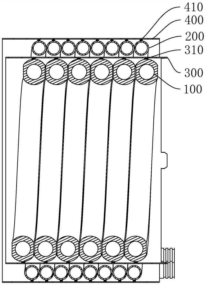
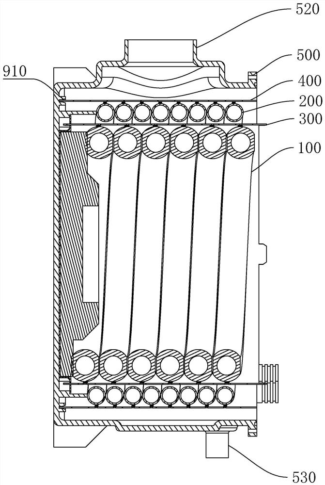
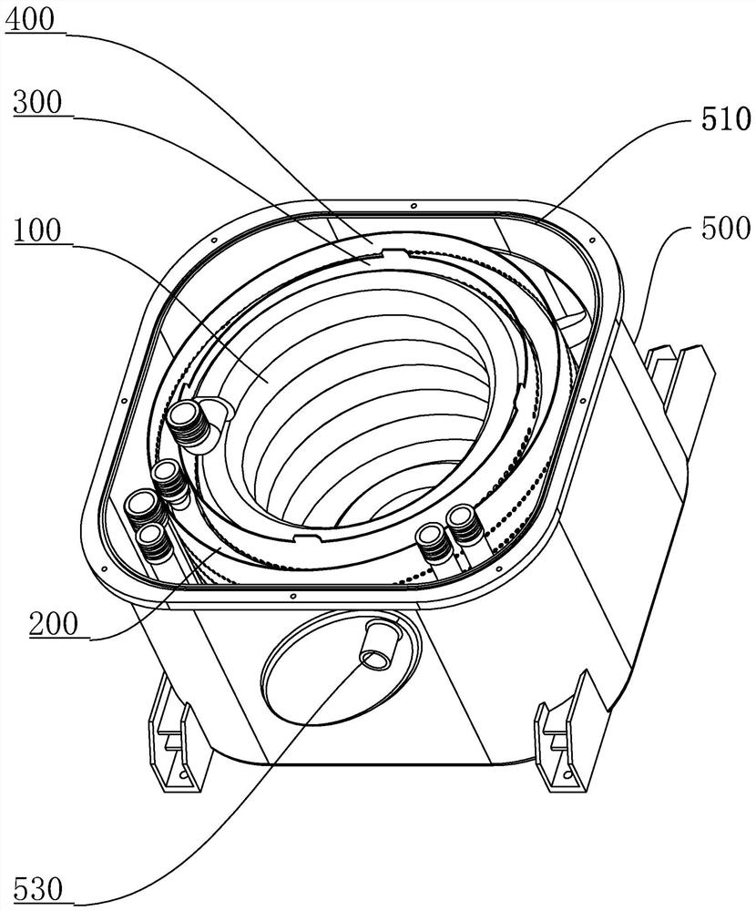
The invention discloses a heat exchange device. The heat exchange device comprises a hollow outer shell, a main heat exchange tube layer, a condensation heat exchange tube layer and a first baffle, wherein the main heat exchange tube layer, the condensation heat exchange tube layer and the first baffle are arranged in the outer shell and are hollow. First fluid channels are formed in the wall bodyof the main heat exchange tube layer, a first gas channel communicating with the inner side and the outer side is formed on the wall body of the main heat exchange tube layer, and the first gas channel is distributed between the first fluid channels; the condensation heat exchange tube layer sleeves the periphery of the main heat exchange tube layer at intervals, and second fluid channels communicating with the first fluid channels are formed in the wall body of the condensation heat exchange tube layer; and the first baffle is located between the main heat exchange tube layer and the condensation heat exchange tube layer, a plurality of first flue gas through holes communicating with the inner side and the outer side are formed in the first baffle, and the plurality of first flue gas through holes are opposite to the first fluid channels and are distributed in the direction of the first fluid channels. According to the heat exchange device, the flue gas temperature distribution is more uniform, the heat exchange is more sufficient, heat waste is reduced, and the heat exchange efficiency is greatly improved.

Description

technical field [0001] The invention relates to a heat exchange device, in particular to a heat exchange device. Background technique [0002] In the prior art, most of the heat exchangers use finned tube heat exchangers, and the combustion chamber part adopts water tube shells. Since the contact surface between the water tubes and the shell is small, the heat available for the water tubes is less, and most of the heat is transferred. To the surface of the shell, the surface temperature of the shell is high, causing a lot of waste of heat, and the heat conversion efficiency is low. Some condensers add a condensing heat exchanger after the main heat exchanger to increase the heat exchange stroke, but the sealing requirements between the main heat exchanger and the condensing heat exchanger are high, and the overall efficiency is difficult to improve. Contents of the invention [0003] The purpose of the present invention is to provide a heat exchange device to solve one or...

Claims


Application Information

Patent Timeline
Patent Type & Authority Applications(China)
IPC IPC(8): F28D7/02F28F9/013
CPCF28D7/022F28F9/0131
Inventor 卢宇聪潘同基岑锦泉李学研李罗标潘泽林
Owner GUANGDONG VANWARD NEW ELECTRIC CO LTD
Why Eureka
Try Eureka