Anti-buckling clamping device, sample and assembling method thereof

A clamping device, anti-buckling technology, applied in the direction of measuring device, using stable tension/pressure test material strength, instrument, etc., can solve the influence uncertainty of data processing, limit the in-depth understanding of materials, material friction coefficient It can avoid buckling instability, break through limitations, and eliminate friction effects.

Pending Publication Date: 2020-10-16
武汉上善仿真科技有限责任公司
View PDF1 Cites 7 Cited by
  • Summary
  • Abstract
  • Description
  • Claims
  • Application Information

AI Technical Summary

Problems solved by technology

[0025] In addition, the existing technology needs to measure the friction coefficient and lateral load to deal with the friction effect, and the friction coefficient of different materials is not the same. Therefore, there is uncertainty in the influence of the treatment of the friction effect on the subsequent test data processing
[0026] Due to the above deficiencies in the existing technology, a deeper understanding of the material itself is limited, and further application in engineering is limited, especially for light metal materials such as aluminum-magnesium alloys with strong tension and compression asymmetry. , and to determine the compressive mechanical properties of thin plate materials is a double-layer challenge in theory and experiment, therefore, it is very important to develop a full-course uniaxial compression test device and its application method for materials

Method used


Image

  • Anti-buckling clamping device, sample and assembling method thereof
  • Anti-buckling clamping device, sample and assembling method thereof
  • Anti-buckling clamping device, sample and assembling method thereof

Examples


Embodiment 1

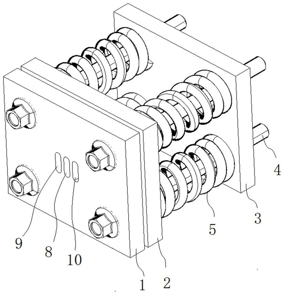
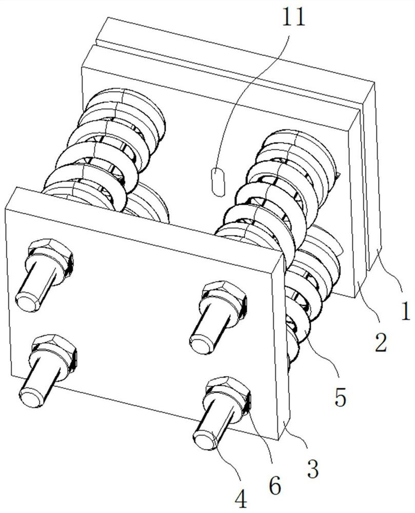
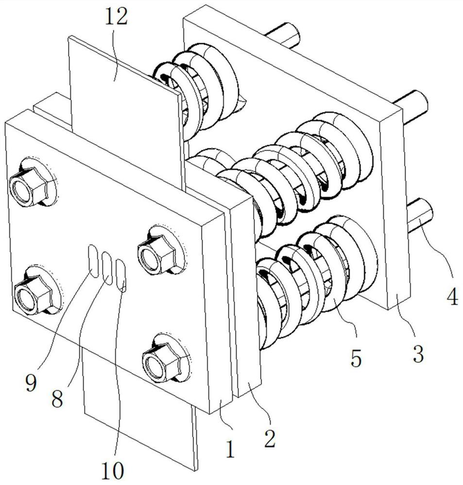
[0094] see Figure 1-7 , the anti-buckling device shown is an embodiment of the present invention, including an outer splint 1, an inner splint 2, a spring pressure plate 3, a bolt 4, a coil spring 5 and a nut 6. The bolt 4 runs through the bolt hole 7 of the outer splint 1, the inner splint 2, and the spring pressure plate 3, wherein the sample 12 is clamped between the outer splint 1 and the inner splint 2 (such as image 3 As shown), the coil spring 5 is clamped between the inner splint 2 and the spring pressure plate 3. The specific method is to insert the coil spring 5 into the bolt 4, and the tail end of the bolt 4 passes through the bolt hole 7 of the spring pressure plate 3, and uses the nut 6 lock (such as figure 2 shown).

[0095] see further image 3 , the outer splint 1 and the middle of the inner splint 2 are respectively provided with an outer state depression 8 (such as Figure 5 shown) and the inner state recess 11 (such as Figure 6 As shown), the centra...

Embodiment 2

[0105] This embodiment provides a sample matched with the anti-buckling clamping device of Embodiment 1, which is characterized in that:

[0106] The sample 12 includes the clamping end 22, the transition zone 23 and the gauge length section 24, and its geometric shape adopts a plane symmetrical design, as shown in FIG. 9 .

[0107] The width of the clamping end 22 is equal to the width of the outer splint 1 , and a bolt gap 25 is provided to realize automatic alignment of the sample 12 and the anti-buckling clamping device in the compression direction.

[0108] The gauge section 24 has a width equal to the distance between the two central axes of the left observation recess 9 and the right observation recess 10, so as to observe the "uniform neck expansion" and "local neck expansion" of the sample 12.

[0109] The position of the bolt notch 25 corresponds to the bolt hole 7 on the outer splint 1, and its width is equal to the diameter of the bolt 6, so as to limit the lateral...

Embodiment 3

[0112] In this embodiment, on the basis of Embodiment 1 and Embodiment 2, the assembly method of the anti-buckling device of the present invention is described in detail, and the steps include:

[0113] In the first step, insert bolts to the outer splint 1. Put the side of the outer splint 1 with the recess facing upwards, insert bolts 4 into each bolt hole of the outer splint 1, and the bolts 4 pass through the bolt holes 7 in the same direction, as shown in Figure 9(a) and Figure 9 (b) shown.

[0114] In the second step, the polytetrafluoroethylene film 13 is arranged. On the side facing the bolt 4, a polytetrafluoroethylene film 13 is placed on the outer splint 1, as shown in Figure 10 (a) and Figure 10 (b), its thickness is 0.1mm, the polytetrafluoroethylene film 13 The plane size of the outer splint is the same as that of the outer splint 1, and the position, size and number of openings on it are consistent with the outer splint 1.

[0115] In the third step, sample 12...


PUM


Abstract

The invention discloses an anti-buckling clamping device. The device comprises an outer clamping plate, an inner clamping plate, a spring pressing plate, a spiral spring, a bolt and a nut, an outer state concave part, a left observation concave part and a right observation concave part are arranged on the outer clamping plate, and an outer state concave part is disposed on the inner clamping plate. Meanwhile, the invention further discloses an assembly method of the anti-buckling clamping device, a sample matched with the anti-buckling clamping device is designed, and the invention further discloses a method for eliminating the friction effect of the anti-buckling clamping device. Through the anti-buckling clamping device, the sample and the assembly method of the anti-buckling clamping device, the deformation measurement range of uniaxial compression test can be expanded, the test cost can be reduced, the device is simple and easy to operate, and meanwhile, the test data obtained by the method subverts the traditional cognition of the Bauschinger effect and expands the depth of scientific research on the material, therefore the anti-buckling clamping device has important theoretical and engineering practice significance.

Description

technical field [0001] The invention relates to the testing of mechanical properties of materials, in particular to the testing of mechanical properties of uniaxial compression of metal materials, in particular to an anti-buckling clamping device, a sample and an assembly method thereof. Background technique [0002] Metal sheets, especially steel sheets and aluminum sheets, as an important raw material, have been widely used in the manufacture of automobile bodies and panels. In order to ensure the reliability of materials and the consistency of production, raw material suppliers and OEMs Such mechanical properties need to be fully demonstrated and researched. Among them, the classic test is the uniaxial tensile test. In contrast, the uniaxial compression test is far less popular than the uniaxial tensile test due to the limitation of the test conditions. research stage. [0003] At present, there are mainly two types of uniaxial compression tests: one is the tension-compr...

Claims


Application Information

Patent Timeline
Patent Type & Authority Applications(China)
IPC IPC(8): G01N3/04G01N3/08G01N3/02
CPCG01N3/02G01N3/04G01N3/08G01N2203/0019G01N2203/027G01N2203/0405
Inventor 肖锋
Owner 武汉上善仿真科技有限责任公司
Why Eureka
Try Eureka