A kind of igbt junction temperature monitoring method, device and system

A junction temperature and test circuit technology, which is applied in the direction of measuring devices, measuring electricity, and measuring electrical variables, etc., can solve the problems of chip junction temperature difference, change heat dissipation conditions and heat dissipation paths, and can not be emitted, and achieve high accuracy.

Active Publication Date: 2022-05-20
ELECTRIC POWER RESEARCH INSTITUTE, CHINA SOUTHERN POWER GRID CO LTD +1
View PDF8 Cites 0 Cited by
  • Summary
  • Abstract
  • Description
  • Claims
  • Application Information

AI Technical Summary

Problems solved by technology

However, in the process of implementing the present invention, the inventors found that the prior art has at least the following problems: the contact test method will damage the device packaging structure, and then change the heat dissipation conditions and heat dissipation paths, resulting in a large difference between the chip junction temperature and the actual situation
Since the chip in the crimp-type IGBT device is completely covered by the collector and emitter plates, the electromagnetic waves radiated by the chip cannot be emitted, so this method is also not suitable for the measurement of the IGBT junction temperature of the sub-module in actual engineering.

Method used


Image

  • A kind of igbt junction temperature monitoring method, device and system
  • A kind of igbt junction temperature monitoring method, device and system
  • A kind of igbt junction temperature monitoring method, device and system

Examples


Embodiment Construction

[0051] The following will clearly and completely describe the technical solutions in the embodiments of the present invention with reference to the accompanying drawings in the embodiments of the present invention. Obviously, the described embodiments are only some, not all, embodiments of the present invention. Based on the embodiments of the present invention, all other embodiments obtained by persons of ordinary skill in the art without creative efforts fall within the protection scope of the present invention.

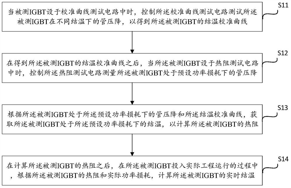
[0052] see figure 1 , is a schematic flowchart of the steps of a method for monitoring the junction temperature of an IGBT provided in Embodiment 1 of the present invention. A method for monitoring the junction temperature of an IGBT provided in Embodiment 1 of the present invention is performed through steps S11 to S14:

[0053] S11. When the IGBT under test is set in the calibration curve test circuit, control the calibration curve test circuit to test the tube ...


PUM


Abstract

The invention discloses a junction temperature monitoring method of an IGBT, which comprises controlling the calibration curve test circuit to test the tube voltage drop of the tested IGBT at different junction temperatures when the tested IGBT is set in the calibration curve test circuit, To obtain the junction temperature calibration curve of the tested IGBT; when the tested IGBT is set in a thermal resistance test circuit, control the thermal resistance test circuit to measure the tube pressure of the tested IGBT under preset power loss and according to the junction temperature calibration curve, obtain the junction temperature of the tested IGBT under the preset power loss to calculate the thermal resistance of the tested IGBT; when the tested IGBT is put into actual engineering operation During the process, the real-time junction temperature of the tested IGBT is calculated according to the thermal resistance and the actual power loss of the tested IGBT. The invention also discloses a corresponding junction temperature monitoring device and system. By adopting the invention, the junction temperature of the IGBT in the operation process can be monitored in real time without affecting the actual engineering operation conditions of the IGBT, and the accuracy of the measurement result is high.

Description

technical field [0001] The invention relates to the technical field of electric power system transmission, in particular to a method, device and system for monitoring the junction temperature of an IGBT. Background technique [0002] The power sub-module is the smallest energy storage and power conversion unit of a modular multilevel converter system (Modular Multilevel Converter, MMC). Its core power device is an insulated gate bipolar transistor (Insulated Gate Bipolar Transistor, IGBT). The main heat generating device when the sub-module is running. According to the device manual, IGBT has a maximum operating junction temperature limit. In order to avoid IGBT overheating and failure due to overload, it is necessary to monitor its junction temperature in real time in order to configure corresponding overheating protection measures. [0003] At present, there are various test methods for IGBT junction temperature, which roughly include three categories: contact method, tem...

Claims


Application Information

Patent Timeline
Patent Type & Authority Patents(China)
IPC IPC(8): G01R31/26
CPCG01R31/2619G01R31/2601Y02E60/60
Inventor 姬煜轲侯婷何智鹏李凌飞杨煜李岩
Owner ELECTRIC POWER RESEARCH INSTITUTE, CHINA SOUTHERN POWER GRID CO LTD
Why Eureka
Try Eureka