High-power device power cycle test junction temperature monitoring method, device and system

A high-power device, power cycle technology, applied in the direction of measuring devices, circuit breaker testing, instruments, etc., can solve the problem of unable to monitor the junction temperature of high-power devices

Active Publication Date: 2021-07-30
CHINA ELECTRONICS PROD RELIABILITY & ENVIRONMENTAL TESTING RES INST
View PDF7 Cites 0 Cited by
  • Summary
  • Abstract
  • Description
  • Claims
  • Application Information

AI Technical Summary

Problems solved by technology

However, during the implementation process, the inventors found that there are at least the following problems in the traditional technology: the traditional power cycle test cannot monitor the junction temperature of high-power devices in real time during the whole process

Method used


Image

  • High-power device power cycle test junction temperature monitoring method, device and system
  • High-power device power cycle test junction temperature monitoring method, device and system
  • High-power device power cycle test junction temperature monitoring method, device and system

Examples


Embodiment Construction

[0046] In order to make the purpose, technical solution and advantages of the present application clearer, the present application will be further described in detail below in conjunction with the accompanying drawings and embodiments. It should be understood that the specific embodiments described here are only used to explain the present application, and are not intended to limit the present application.

[0047] In a specific application scenario of the high-power device power cycle test junction temperature monitoring method of this application:

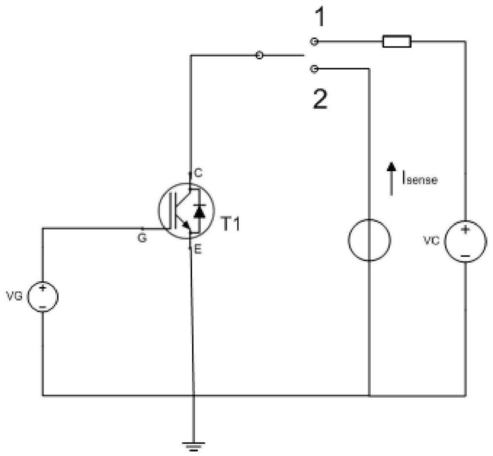
[0048] In the traditional technology, the small current injection conduction voltage drop method is usually used to measure the junction temperature during the power cycle test. The specific steps are: firstly apply a large heating power to the device to cause the device to heat up, and then cut off the heating power instantaneously, apply A very small test current (usually 10-100mA) that does not cause self-heating temperature r...


PUM


Abstract

The present application relates to a method, device and system for monitoring the junction temperature of a power cycle test of a high-power device. The method includes: when controlling the power supply equipment to power on the device under test based on preset test parameters, using a transient junction temperature monitoring model to process the case temperature and power loss to obtain the first type of junction temperature; When the operation is stable, use the large current temperature-sensitive parameter model to process the conduction current value and conduction voltage value to obtain the second type of junction temperature; when the temperature rise time is over and the increase value of the junction temperature of the device under test reaches the preset value When the small current temperature-sensitive parameter model is used to process the variation of the conduction voltage to obtain the third type of junction temperature; when the cooling time is monitored and the junction temperature reduction value of the device under test reaches the preset value, the test times are accumulated Once, until the number of tests reaches the preset number or the device under test fails, so as to realize the real-time monitoring of the junction temperature of the device under test from power-on to power-off to cool down.

Description

technical field [0001] The present application relates to the technical field of high-power device performance detection, in particular to a method, device and system for monitoring junction temperature of high-power device power cycle test. Background technique [0002] IGBT (Insulated Gate Bipolar Transistor, Insulated Gate Bipolar Transistor), MOSFET (Metal-Oxide-Semiconductor Field-Effect Transistor, Metal-Oxide-Semiconductor Field-Effect Transistor) and other high-power switching devices are in the on-off working state for a long time. Under on-off working conditions, the junction temperature of high-power switching devices will change greatly. Since the high-power switching device is composed of multiple layers of materials with different thermal expansion coefficients, when the temperature changes, the thermal expansion and contraction of the material will generate a large shear stress at the interface, causing the original defects to gradually expand, making the conn...

Claims


Application Information

Patent Timeline
Patent Type & Authority Patents(China)
IPC IPC(8): G01R31/327G01R31/00
CPCG01R31/00G01R31/327
Inventor 陈媛张鹏周斌陈义强贺致远
Owner CHINA ELECTRONICS PROD RELIABILITY & ENVIRONMENTAL TESTING RES INST
Why Eureka
Try Eureka