Eureka AIR delivers breakthrough ideas for toughest innovation challenges, trusted by R&D personnel around the world.

CAN communication module control monitoring system based on C #

A CAN communication and module control technology, applied in the direction of inter-program communication, program control design, program control device, etc., can solve the problems of complicated modification of control instructions and inability to grasp module dynamics in real time.

Pending Publication Date: 2020-10-16
LIYANG HUAPENG ELECTRIC POWER METER
View PDF4 Cites 0 Cited by
  • Summary
  • Abstract
  • Description
  • Claims
  • Application Information

AI Technical Summary

Problems solved by technology

Unable to grasp module dynamics in real time
The way to modify the control instruction is complex

Method used


Image

  • CAN communication module control monitoring system based on C #

Examples


Embodiment Construction

[0021] The present invention will be described in detail below in conjunction with the accompanying drawings and specific embodiments.

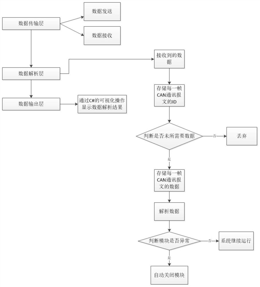
[0022] Such as figure 1 As shown, a C#-based CAN communication module control and monitoring system includes a data transmission layer, a data analysis layer, and a data output layer, and the data transmission layer, data analysis layer, and data output layer are connected in sequence.

[0023] The data transmission layer: the system is set by programming to transmit the CAN frame through the bus, including the data type of the interface card information, the data type of the CAN information frame, and the data type of the initialization CAN;

[0024] When sending data, configure relevant parameters on the program interface through the visual operation of C#: CAN type, CAN channel, baud rate, filter and working mode, and select the sending command, and the system sets the ID of the sent data frame according to the function defined by the prog...


PUM


Abstract

The invention discloses a CAN communication module control monitoring system based on C #. The system comprises a data transmission layer, a data analysis layer, and a data output layer, which are connected in sequence. Complex data sent by the module can be screened, classified and analyzed, the module can be set in real time, the state of the module can be monitored, and non-professionals can visually understand information of the module.

Description

technical field [0001] The invention relates to the field of automobile computer control and embedded development, in particular to a C#-based CAN communication module control and monitoring system. Background technique [0002] With the gradual prevalence of new energy vehicles, the status of the CAN bus protocol in the automotive industry is becoming more and more important. Its hardware message filtering function can greatly reduce the burden on the CPU. On this basis, in order to obtain the information of the module, various USB_CAN TOOL tool software also emerges as the times require. Using the CANalyst-II analyzer, these software can realize the sending and receiving of CAN bus network data through the USB interface of the computer. [0003] The existing technology can only mechanically send and receive the messages sent by the module. The obtained message needs to be processed by professionals to analyze the data. It is impossible to grasp the module dynamics in re...

Claims


Application Information

Patent Timeline
Patent Type & Authority Applications(China)
IPC IPC(8): G06F9/445G06F9/54G06F11/30
CPCG06F9/4451G06F9/547G06F11/302
Inventor 戴诚姜逸欢冷鹏飞冷鹏程马剑尹青蒋小丹何浩
Owner LIYANG HUAPENG ELECTRIC POWER METER
Why Eureka
Eureka Blog
Learn More