
Electromagnetic operating mechanism and circuit breaker with same

A technology of electromagnetic operation and electromagnetic drive, which is applied in the direction of protection switch operation/release mechanism, circuit, contact drive mechanism, etc. It can solve the problems of inability to meet the test standards, slow operating mechanism, and large size of accessories, and achieve compact structure, Reduce the effect of zero mechanism and few components

Pending Publication Date: 2020-10-16
KEDU ELECTRIC CO LTD
View PDF0 Cites 0 Cited by
  • Summary
  • Abstract
  • Description
  • Claims
  • Application Information

AI Technical Summary

Problems solved by technology

[0002] The operating mechanism of the existing intelligent circuit breaker has two structures. One is an independent electric operating mechanism, which is installed on the plastic case circuit breaker (MCCB) as an independent accessory. The cost is very high; the other is the operating mechanism designed in the MCCB, using the motor as the driving source, but the speed of this operating mechanism is too slow to meet the test standards

Method used


Image

  • Electromagnetic operating mechanism and circuit breaker with same
  • Electromagnetic operating mechanism and circuit breaker with same
  • Electromagnetic operating mechanism and circuit breaker with same

Examples


Embodiment 1

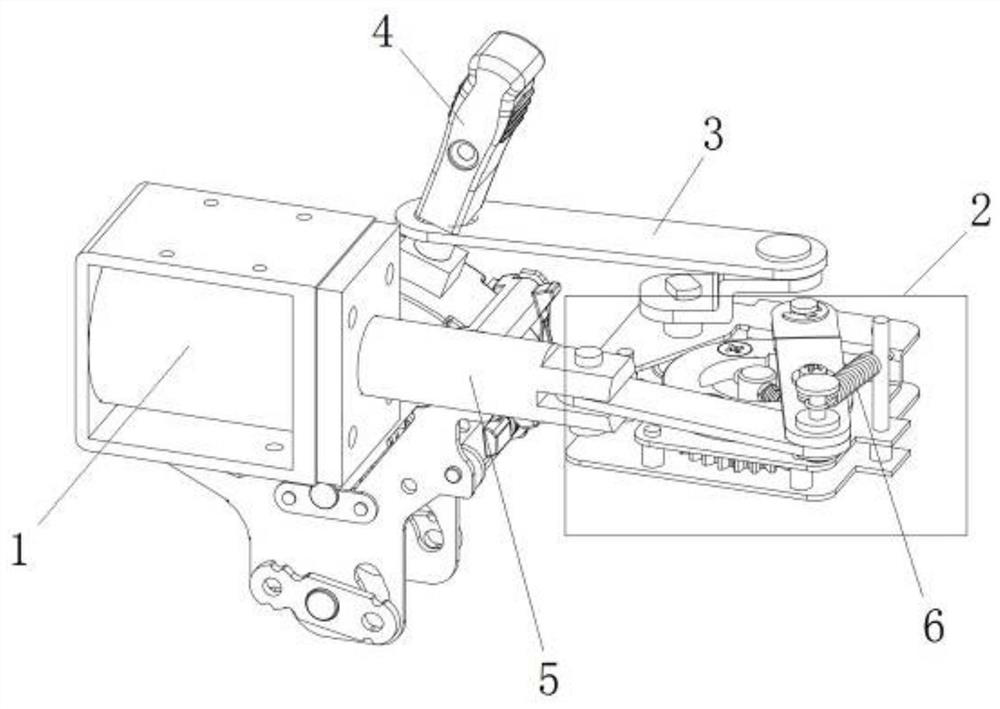
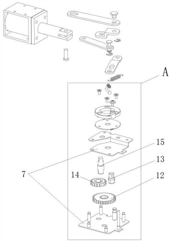
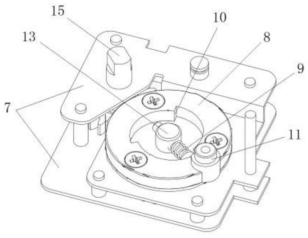
[0080] This embodiment provides a specific implementation of the electromagnetic operating mechanism, such as figure 1 As shown, it includes: an electromagnetic driver 1, a power conversion mechanism 2 and a pull rod 3. The power conversion mechanism 2 is used to convert the attraction force of the electromagnetic driver 1 into a reciprocating driving force for the closing handle 4 of the switch. Wherein, the moving iron core 5 of the electromagnetic driver 1 is also connected with a first elastic member 6, and the first elastic member 6 has a restoring force to drive the moving iron core 5 to move toward the release direction, that is: when the electromagnetic driver When 1 is released, the moving iron core 5 can be pulled out of the coil under the action of the first elastic member 6, which is a tension spring.

[0081] Such as figure 2 , image 3 As shown, the power conversion mechanism 2 includes: a ratchet mechanism and a gear mechanism, the gear mechanism is sandwich...

Embodiment 2

[0100] This embodiment provides a specific implementation of the electromagnetic operating mechanism, such as Figure 19 As shown, it includes: an electromagnetic driver 1, a power conversion mechanism 2 and a pull rod 3. The power conversion mechanism 2 is used to convert the attraction force of the electromagnetic driver 1 into a reciprocating driving force for the closing handle 4 of the switch. Wherein, the moving iron core 5 of the electromagnetic driver 1 is also connected with a first elastic member 6, and the first elastic member 6 has a restoring force to drive the moving iron core 5 to move toward the release direction, that is: when the electromagnetic driver When 1 is released, the moving iron core 5 can be pulled out of the coil under the action of the first elastic member 6, which is a torsion spring.

[0101] Such as Figure 19 , Figure 20 As shown, the power conversion mechanism 2 includes: a ratchet mechanism and a gear mechanism, the gear mechanism is dir...

Embodiment 3

[0115] This embodiment provides a specific implementation of a circuit breaker, including the electromagnetic operating mechanism described in Embodiment 1 or Embodiment 2, wherein the switch closing handle 4 of the circuit breaker is hingedly connected to the pull rod 3 of the electromagnetic operating mechanism.


PUM


Abstract

The invention provides an electromagnetic operating mechanism and a circuit breaker with the same, and belongs to the technical field of electrical parts. The electromagnetic operating mechanism comprises an electromagnetic driver, a first elastic part, a ratchet mechanism and a pull rod, and the first elastic part has restoring force for driving a movable iron core to move towards a release direction; a driving piece of the ratchet mechanism is connected with the movable iron core, and a driven piece is suitable for unidirectional rotation under the driving of the driving piece; and one end of the pull rod is connected with a driven member of the ratchet mechanism, and the other end is suitable for connecting with a switch closing handle. According to the electromagnetic operating mechanism, the electromagnetic driver is driven by the intelligent control circuit, the automatic switching-on or switching-off speed is high, the contact mechanism can be instantly switched on or switched off, the contact or switching-off time of the contact mechanism is shortened, the burning loss of an electric arc to a contact is obviously reduced, and the service life of a switch is prolonged.

Description

technical field [0001] The invention relates to the technical field of electrical components, in particular to an electromagnetic operating mechanism and a circuit breaker with the same. Background technique [0002] The operating mechanism of the existing intelligent circuit breaker has two structures. One is an independent electric operating mechanism, which is installed on the plastic case circuit breaker (MCCB) as an independent accessory. The cost is very high; the other is an operating mechanism designed in the MCCB and uses a motor as a driving source, but the speed of this operating mechanism is too slow to meet the test standards. Contents of the invention [0003] Therefore, the technical problem to be solved by the present invention is to overcome the defect that the operating mechanism in the prior art is driven by a motor and the speed is too slow, so as to provide an electromagnetic operating mechanism. [0004] The present invention also provides a circuit ...

Claims


Application Information

Patent Timeline
Patent Type & Authority Applications(China)
IPC IPC(8): H01H71/24H01H71/52H01H3/34H01H3/40
CPCH01H3/34H01H3/40H01H71/24H01H71/521
Inventor 郑春开徐高明廖军林建荣万成义
Owner KEDU ELECTRIC CO LTD
Learn More