
Modularized power supply box

A modular power supply and technology within the module, which is applied to circuits, electrical components, battery pack components, etc., can solve the problems of damage to the battery outer skin, high development cost, long cycle, etc. The effect of reducing cost and cycle time

Inactive Publication Date: 2020-10-16
BENGBU SHUYANG ELECTRONICS TECH
View PDF0 Cites 0 Cited by
  • Summary
  • Abstract
  • Description
  • Claims
  • Application Information

AI Technical Summary

Problems solved by technology

[0003] The technical problem to be solved by the present invention is to provide a modular power supply box, which solves the problem of high development cost, long cycle, and battery skin damage or short circuit caused by injection molding with a fixed structure.

Method used


Image

  • Modularized power supply box
  • Modularized power supply box
  • Modularized power supply box

Examples


Embodiment Construction

[0027] The following will clearly and completely describe the technical solutions in the embodiments of the present invention with reference to the accompanying drawings in the embodiments of the present invention. Obviously, the described embodiments are only some, not all, embodiments of the present invention. Based on the embodiments of the present invention, all other embodiments obtained by persons of ordinary skill in the art without making creative efforts belong to the protection scope of the present invention.

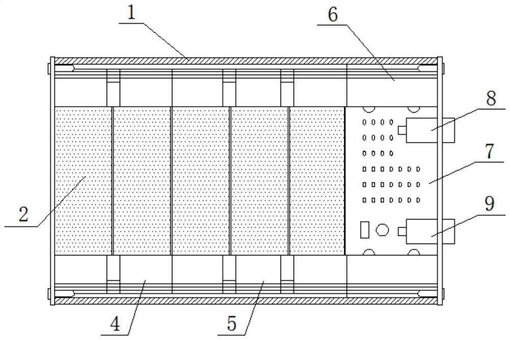
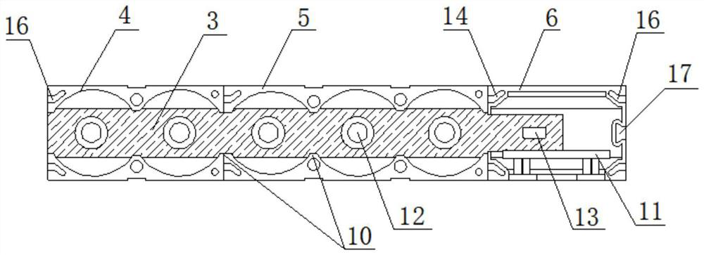
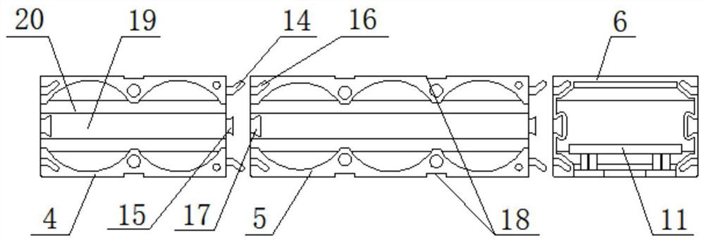
[0028] See Figure 1-Figure 4, a modular power supply box, including a shell 1, five cylindrical batteries 2, two pole plates 3, two two-position battery slot modules 4, two three-position battery slot modules 5, Two bidirectional terminal modules 6 and a circuit board 7; the circuit board 7 is connected with an input interface 8 and an output interface 9 whose outer end extends out of the shell 1; two two-position battery slot modules 4, two three-position ba...


PUM


Abstract

The invention discloses a modular power supply box. The modular power supply box comprises a shell, a battery arranged in the shell, polar plates and battery jar modules, each battery jar module is ofa U-shaped structure; and the two ends of each battery jar module are provided with a buckle and a clamping groove respectively. Every two adjacent battery jar modules are clamped with each other through a buckle and clamping groove structure; the plurality of battery jar modules are clamped to form a communicated integral U-shaped groove, the corresponding polar plate is arranged in the integralU-shaped groove, the end part of each battery is embedded into a battery positioning groove of the corresponding battery jar module, and two poles of each battery are in contact connection with elastic contacts of the embedded polar plate in the battery jar module. The batteries can be assembled and combined according to the number of the batteries in the power supply box, accurate connection ofthe batteries and the polar plates is achieved, and the connection structure is stable and safe.

Description

technical field [0001] The invention relates to the field of mobile power supplies, in particular to a modular power supply box. Background technique [0002] At present, the battery box on the market usually adopts fixed structure injection mold opening, the early development cost is high, and the cycle is long. For some small batches or special products, there are various requirements, such as multi-section parallel connection, series connection, multi-section series-parallel connection, It is impossible to open a mold for every product, which wastes a lot of time and money. Moreover, the product is upgraded quickly and the structure is changeable. It is easy to be restrained or eliminated by using a fixed method. Obviously, it cannot meet the needs of the industry. This structure also has disadvantages. Especially for some high-power battery boxes, the two ends of the battery use springs or nickel sheets with strong elasticity as contacts. When disassembling, it is necess...

Claims


Application Information

Patent Timeline
IPC IPC(8): H01M2/10H01M2/20
CPCY02E60/10
Inventor 杨海燕
Owner BENGBU SHUYANG ELECTRONICS TECH
Learn More