Automatic feeding device for livestock breeding
An automatic feeding and livestock technology, applied in the field of livestock breeding, can solve the problems of unfavorable addition and supplementation of other nutrients, lack of scientific and advanced management technology, etc., to avoid manual addition, avoid untimely filling, and improve automation degree of effect
- Summary
- Abstract
- Description
- Claims
- Application Information
AI Technical Summary
Problems solved by technology
Method used
Image

Examples
Embodiment
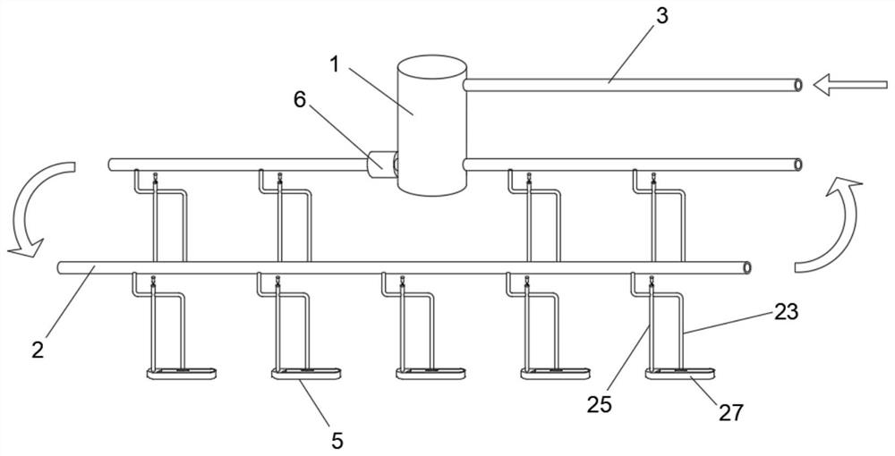
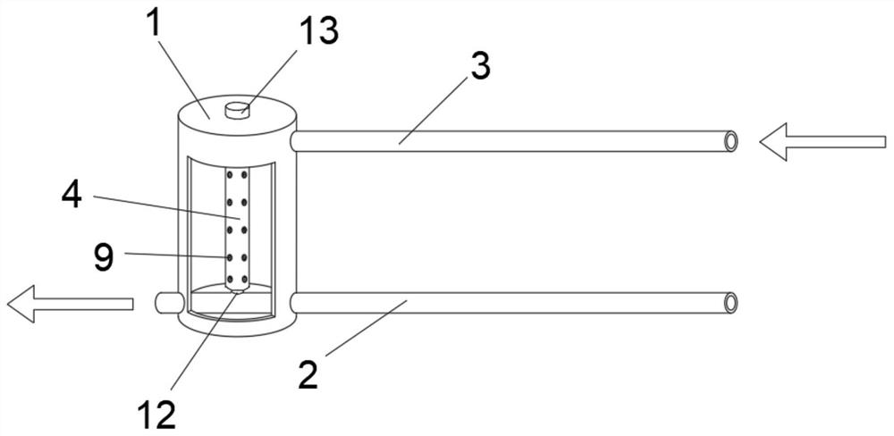
[0032] Such as Figure 1-7 As shown, an automatic feeding equipment for livestock breeding, including a water injection cylinder 1 and a diversion tube 2, the water injection cylinder 1 is provided with a cavity and is a closed cylinder, the diversion tube 2 is a closed loop, and the diversion tube 2 and the The water injection cylinder 1 is fixedly connected and arranged in communication. One end of the water injection cylinder 1 is fixedly connected with a water inlet pipe 3 on the side wall, and one end of the water inlet pipe 3 is connected to an external water supply device. A water filtering mechanism 4 is arranged in the water injection cylinder 1 .
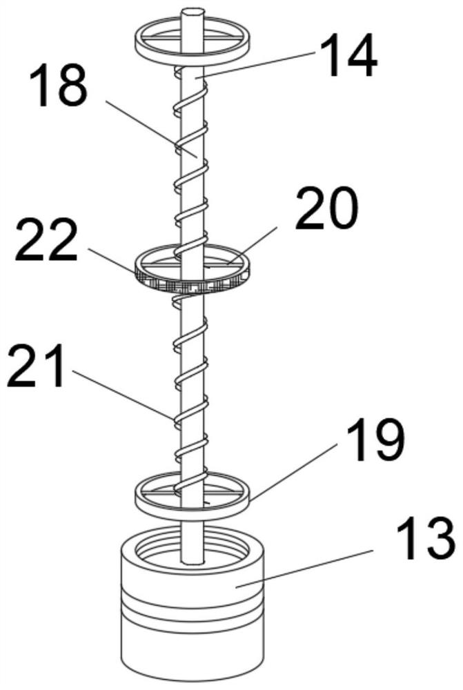
[0033] One end of the water filter mechanism 4 is fixedly connected with the guide pipe 2, and the other end of the water filter mechanism 4 penetrates the top surface of the water injection cylinder 1 and extends to the outside thereof. The water filter mechanism 4 includes a filter cartridge arranged in the water injecti...
PUM
 Abstract
Description
Claims
Application Information
PatSnap Eureka turns technology decisions into work you can execute. Powered by our Innovation Knowledge Graph, it runs expert workflows across engineering, life sciences, materials and intellectual property. Get your review-ready output in minutes.


