Floating powder suction device for pressed powder

A technology for floating powder and powder cake, which is applied in the directions of cleaning methods and utensils, chemical instruments and methods, cleaning methods using gas flow, etc.

Pending Publication Date: 2020-10-20
范芳芳
View PDF7 Cites 2 Cited by
  • Summary
  • Abstract
  • Description
  • Claims
  • Application Information

AI Technical Summary

Problems solved by technology

[0004] In order to overcome the disadvantages of manually moving the dust suction pipe repeatedly and manually fixing the powder cake in the way of manually sucking floating powder, the technical problem of the present invention is to provide a method that can automatically move the dust suction pipe and automatically fix the powder cake, A powder cake suction and floating powder device that realizes automatic suction and floating powder

Method used


Image

  • Floating powder suction device for pressed powder
  • Floating powder suction device for pressed powder
  • Floating powder suction device for pressed powder

Examples


Embodiment 1

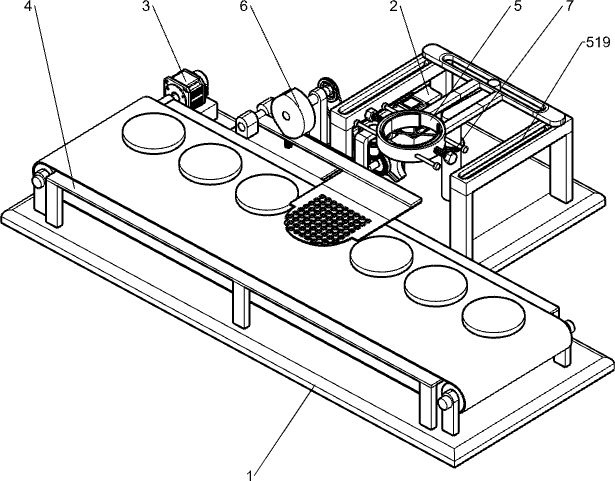
[0038] A powder suction floating powder device, such as figure 1 As shown, it includes a base 1, a drive motor 2, a material transport mechanism 3, a working plate 4 and an intermittent mechanism 5. The drive motor 2 is installed on the left side of the rear side of the base 1, and the material transport mechanism 3 is provided on the front side of the base 1. The base 1 The front side is provided with a working plate 4, and an intermittent mechanism 5 is installed on the rear side of the base 1, and the intermittent mechanism 5 is connected with the driving motor 2.

[0039] When it is necessary to absorb the floating powder on the powder cake, first place the powder cake on the parts of the material conveying mechanism 3, put the dust suction pipe of the vacuum cleaner into the parts of the intermittent mechanism 5 from top to bottom, and then manually start the drive motor 2 and the material conveying mechanism. The parts in the mechanism 3, the feeding mechanism 3 drives t...

Embodiment 2

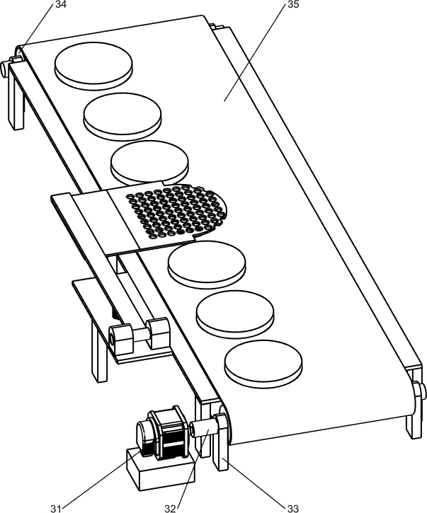
[0041] refer to Figure 1-2 and Figure 4-5 As shown, the feeding mechanism 3 includes a feeding motor 31, a feeding rotating shaft 32, a first support rod 33, a feeding drum 34 and a feeding belt 35, and the left side of the base 1 is equipped with a feeding motor 31, and the feeding motor 31 Intermittent operation, two first support rods 33 are arranged on the left and right sides of the front part of the base 1, and the upper part of the first support rod 33 on the same side is provided with a material delivery shaft 32 in a rotating manner, and the rear side of the left side material delivery shaft 32 The upper part is connected with the output shaft of the feeding motor 31, the feeding drum 34 is arranged on the feeding rotating shaft 32, and the feeding belt 35 is wound between the feeding drums 34 on both sides, and the upper feeding belt 35 is located at the working position. plate 4.

[0042] The powder cake is placed on the material conveying belt 35, then start th...

Embodiment 3

[0046] Specifically, such as Figure 2-3 As shown, a powder pressing mechanism 6 is also included. The powder pressing mechanism 6 includes a support plate 61, a second rotating shaft 62, a second belt assembly 63, a cam 64, a mounting seat 65, a pressing plate 66 and a second spring 67. The left side of the base 1 The rear part is provided with a support plate 61, the upper part of the support plate 61 is rotatably equipped with a second rotating shaft 62, a second belt assembly 63 is connected between the rear side of the second rotating shaft 62 and the front side of the transmission shaft 51, and the front end of the second rotating shaft 62 is provided with Cam 64, mounting seat 65 is arranged on the left side rear part of working plate 4, and mounting seat 65 is provided with pressing plate 66 swingingly, and cam 64 is in contact with pressing plate 66, and second spring 67 is connected between the bottom of pressing plate 66 and working plate 4 tops .

[0047] After st...


PUM


Abstract

The invention relates to a floating powder suction device, in particular to a floating powder suction device for pressed powder. The floating powder suction device aims at achieving the technical purposes that a powder suction pipe can automatically move, pressed powder can be automatically fixed, and floating powder suction automation is achieved. According to the technical scheme, the floating powder suction device comprises a base and an intermittent mechanism, wherein a driving motor is installed on the rear side of the base, a powder conveying mechanism is arranged on the front side of the base, a working plate is installed on the front side of the base, the intermittent mechanism is arranged on the side, close to one side of the driving motor, of the base, and the intermittent mechanism is connected with the driving motor. The powder conveying mechanism drives the pressed powder to intermittently rotate, automatic replacement of the pressed powder is achieved, the powder suctionpipe does not need to be manually moved, the intermittent mechanism drives the powder suction pipe to intermittently move front and back, automatic floating powder suction of the powder suction pipe is achieved, the pressed powder is fixed through a powder pressing mechanism, the pressed powder does not need to be manually fixed, and the floating powder can be conveniently sucked away through thepowder suction pipe.

Description

technical field [0001] The invention relates to a powder suction and floating device, in particular to a powder cake suction and floating powder device. Background technique [0002] After the powder cake manufacturer produces the powder cake, some floating powder will remain on the surface of the powder cake, which will affect the appearance of the powder cake. In order to remove the floating powder on the powder cake, the worker will hold the suction pipe of the vacuum cleaner in one hand and the mesh pressure plate in the other. Use the pressure plate to fix the powder cake, then place the vacuum tube on the pressure plate, and then the vacuum tube will suck off the floating powder on the powder cake, and then manually move the pressure plate and vacuum tube to suck the floating powder for the next powder cake. [0003] The above-mentioned method of artificially sucking the floating powder on the powder cake requires manual control of the suction tube and repeated movemen...

Claims


Application Information

Patent Timeline
IPC IPC(8): B08B5/04B08B13/00
CPCB08B5/04B08B13/00
Inventor 范芳芳
Owner 范芳芳
Why Eureka
Try Eureka