
Mechanical feeding device

A technology for mechanical and installation columns, which is applied in the field of mechanical loading devices, and can solve problems such as delays in parcel transportation time

Inactive Publication Date: 2020-10-20
覃虎
View PDF0 Cites 2 Cited by
  • Summary
  • Abstract
  • Description
  • Claims
  • Application Information

AI Technical Summary

Problems solved by technology

[0003] The delivery of express parcels in the warehouse is undertaken by the conveyor. Usually, multiple conveyors cooperate to transmit the parcels. Due to the structural defects of the conveyors, small parcels are easily stuck at the junction of the two conveyors, and the parcels are formed here. The grooves are turned over and cannot be sent out. It often takes many days to be discovered by the staff, which delays the transportation time of a lot of packages. Therefore, a feeding device is urgently needed to solve such problems.

Method used


Image

  • Mechanical feeding device
  • Mechanical feeding device
  • Mechanical feeding device

Examples


Embodiment 1

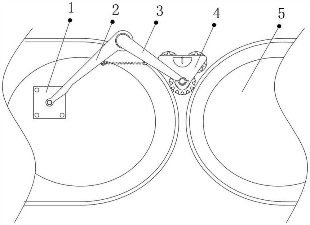
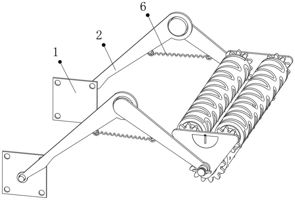
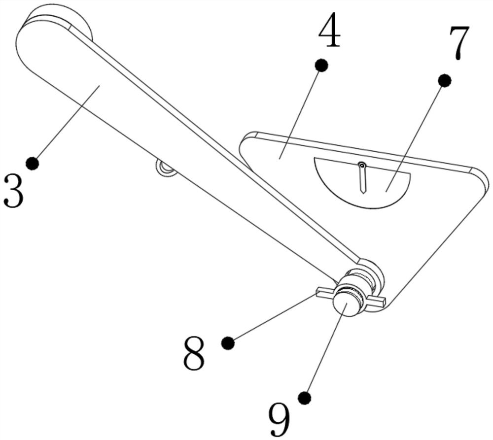
[0033] refer to Figure 1-6 , a mechanical feeding device, comprising a balance plate 4, a transmission mechanism is arranged on one side of the balance plate 4, and the transmission mechanism outer wall is connected with a transmission disc 13, and the outer wall of the transmission disc 13 is welded with a plurality of limit columns 14, The outer wall of the transmission plate 13 is clamped with the connecting plate 11, and the outer wall of the connecting plate 11 is provided with a plurality of limit holes 12, and the limit holes 12 are adapted to the limit posts 14, and the outer walls of one side of the connecting plate 11 are respectively welded. There are a fixed frame 18 and a transmission roller shaft 22, the outer wall of the fixed frame 18 is welded with a conveying roller shaft 17, and the conveying roller shaft 17 is set in a tubular shape, and the outer wall of the conveying roller shaft 17 is provided with a plurality of slag discharge holes 16, and the conveyin...

Embodiment 2

[0037] refer to Figure 7 , a mechanical feeding device. Compared with Embodiment 1, the outer wall of the balance plate 4 is connected with a waste residue box 25 by bolts, and the inner wall of the waste residue box 25 is connected with a cleaning plate by bolts, and the outer wall of the cleaning plate is provided with There is a hair brush 26, and the hair brush 26 is in contact with the drive roller shaft 22.

[0038]Working principle: When in use, the device is installed on the conveyor 5, and due to the elastic force of the tension spring 6, the driving roller shaft 22 will be pressed tightly on the conveyor belt of the conveyor 5, and the balance is adjusted with the assistance of the vertical measuring instrument 7 plate 4, so that its center of gravity is vertically downward, so as to ensure the balance of the device during operation. The volume of the device is small, and the height of the upper surface of the conveying roller shaft 17 is lower than that of the conv...


PUM


Abstract

The invention discloses a mechanical feeding device. The mechanical feeding device comprises a balance plate; a transmission mechanism is arranged on the outer wall of one side of the balance plate, atransmission disc is connected to the outer wall of the transmission mechanism, a plurality of limiting columns are fixed to the outer wall of the transmission disc, a connecting disc is clamped to the outer wall of the transmission disc, a plurality of limiting holes are formed in the outer wall of the connecting disc, and the plurality of limiting holes are matched with the plurality of limiting columns; a fixing frame and a transmission roller shaft are fixed to the outer wall of one side of the connecting disc, conveying roller shafts are fixed to the outer wall of the fixing frame, and the conveying roller shafts are arranged to be tubular. According to the mechanical feeding device, the defect that small packages are prone to being clamped at the joint of a traditional conveyor is overcome, the device operates through transmission of the conveyor, electric energy consumption is not needed, energy conservation and environmental protection are achieved, in addition, one transmission roller shaft is arranged to drive the two conveying roller shafts, the conveying roller shafts operate in the conveying direction of the conveyor all the time, adjustment is not needed, and use isconvenient; the gravity center of a regular triangular balancing weight is stable, and the transmission effect of the transmission roller shaft can be improved.

Description

technical field [0001] The invention relates to the technical field of material transmission, in particular to a mechanical feeding device. Background technique [0002] With the popularity of online shopping, the express delivery industry is becoming more and more developed. Express delivery, also known as express delivery or express delivery, refers to the logistics companies that use their own independent network or in the form of joint venture cooperation to quickly and safely send documents or packages entrusted by users A new mode of transportation from person to recipient. [0003] The delivery of express parcels in the warehouse is undertaken by the conveyor. Usually, multiple conveyors cooperate to transmit the parcels. Due to the structural defects of the conveyors, small parcels are easily stuck at the junction of the two conveyors, and the parcels are formed here. The groove of the package is turned over and cannot be sent out. It often takes many days to be dis...

Claims


Application Information

Patent Timeline
IPC IPC(8): B65G47/52B65G39/02B65G39/10B65G45/18B65G45/26
CPCB65G39/02B65G39/10B65G45/18B65G45/26B65G47/52
Inventor 覃虎
Owner 覃虎
Learn More