Steel-concrete composite beam structure, building and construction method

A technology of concrete and composite beams, which is applied to building structures, buildings, building components, etc., and can solve problems such as complex construction, complex construction technology, and large steel consumption

Inactive Publication Date: 2020-10-20
SHANDONG JIANZHU UNIV +2
View PDF11 Cites 2 Cited by
  • Summary
  • Abstract
  • Description
  • Claims
  • Application Information

AI Technical Summary

Problems solved by technology

[0005] However, the inventor found that the steel beam part of the existing composite beam needs to be provided with a large number of stiffeners, the construction is complicated, the steel consumption is large, the plane stiffness and shear buckling resistance capacity are poor,

Method used


Image

  • Steel-concrete composite beam structure, building and construction method
  • Steel-concrete composite beam structure, building and construction method
  • Steel-concrete composite beam structure, building and construction method

Examples


Embodiment 1

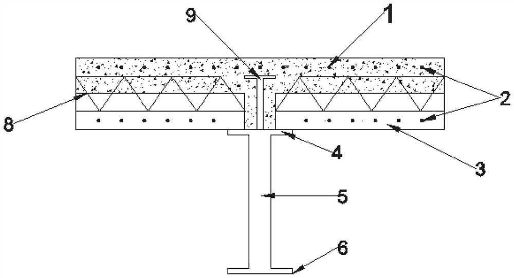
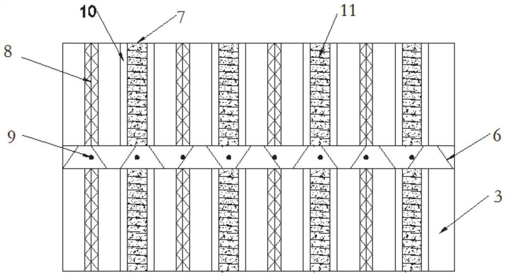
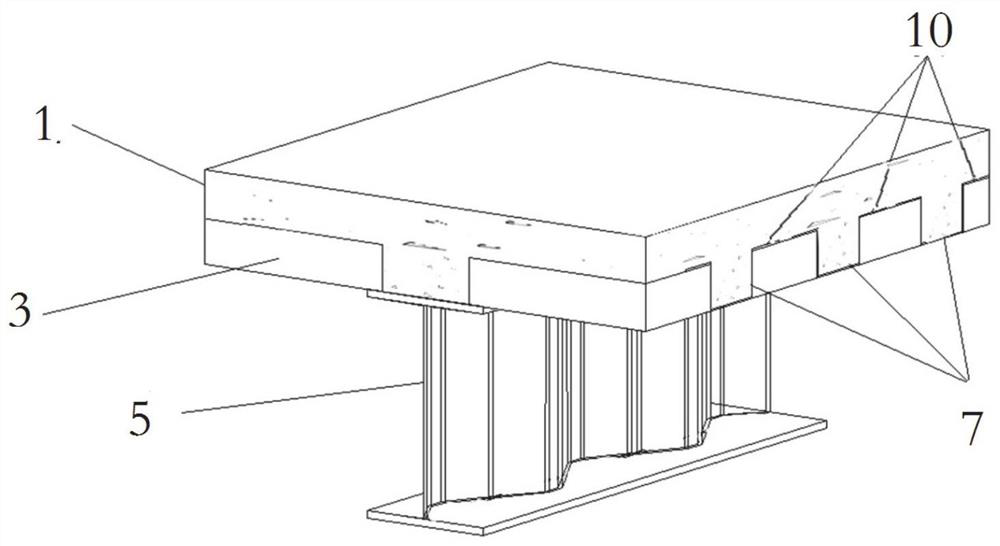
[0029] Such as Figure 1-5 As shown, this embodiment provides a steel-concrete composite beam structure, including a corrugated web steel girder, the upper surface of the upper flange of the corrugated web steel girder is lapped with a prefabricated slab 3, and a joint 7 is formed between adjacent prefabricated slabs 3 Concrete is poured in the joint 7, and the adjacent prefabricated slabs 3 are connected by lap steel bars 11 and profiled steel plates 10. The upper end surface of the prefabricated slab 3 is provided with a post-cast layer 1, and the post-cast layer 1 is formed with the precast slab 3. Composite plate structure; a profiled steel plate 10 is arranged in the joint 7 , and the bottom surface of the profiled steel plate 10 is flush with the lower end surface of the prefabricated plate 3 to receive the concrete in the joint 7 .

[0030] It should be pointed out that in this embodiment, the overlapping steel bars can be bound by wire ropes or pulled by U-shaped steel...

Embodiment 2

[0044] This embodiment provides a construction method for a steel-concrete composite beam structure, comprising the following steps:

[0045] Step 1, fix the corrugated web steel girder, and weld the fixed shear connector on the upper flange;

[0046] Step 2, the prefabricated slab 3 is lapped on the upper surface of the upper flange of the corrugated web steel girder, the prefabricated slab 3 is supported by the preset bracket, and a certain length of lapped steel bars is reserved at the splicing part of the adjacent prefabricated slabs, and the lapped The position of the steel bar is also the joint position between adjacent prefabricated panels. And place profiled steel plates at the seams to connect the two prefabricated panels. The width of the bottom plate of the profiled steel plate is the same as that of the seam, the height of the left and right webs is the same as that of the prefabricated slab, and the length is the same as the span of the prefabricated slab. And the...

Embodiment 3

[0053] This embodiment provides a building using the steel-concrete composite beam structure described in Embodiment 1. The building in this embodiment can be a bridge or a prefabricated house, etc., and those skilled in the art can choose the application occasion of the composite beam by themselves, which will not be repeated here.


PUM


Abstract

The invention relates to a steel-concrete composite beam structure, a building and a construction method. The structure comprises a corrugated web steel beam. A prefabricated slab is in lap joint withthe upper surface of the upper flange of the corrugated web steel beam. An edge joint is formed between every two adjacent prefabricated slabs. Concrete is poured into the edge joints. The adjacent prefabricated slabs are connected through lap joint steel bars. A post-cast layer is arranged on the upper end face of the prefabricated slab. The post-cast layer and the prefabricated slab form a composite slab structure. A profiled steel sheet is arranged in the edge joint. The bottom face of the profiled steel sheet is flush with the lower end face of the prefabricated slab so as to bear the concrete in the edge joints. According to the steel-concrete composite beam structure, the building and the construction method, the structural strength and integrality of the composite beam can be improved, meanwhile, laying of templates is reduced, the construction technique is simplified, and the construction efficiency is improved.

Description

technical field [0001] The disclosure belongs to the technical field of construction engineering, and in particular relates to a steel-concrete composite beam structure, a building and a construction method. Background technique [0002] The statements herein merely provide background information related to the present invention and do not necessarily constitute prior art. [0003] The steel-concrete composite beam refers to the bending-resistant member that connects the steel beam and the concrete slab as a whole through the shear connector and works together. When the composite beam is subjected to a positive bending moment, the concrete slab is in the compression zone, and most of the steel beam is in the tension zone, so the respective mechanical properties of the two materials can be fully utilized. Compared with reinforced concrete beams, composite beams can greatly reduce the weight of the structure, have a larger span-to-height ratio, and facilitate construction; co...

Claims


Application Information

Patent Timeline
IPC IPC(8): E04B5/02E04B5/10
CPCE04B5/023E04B5/10
Inventor 吕俊利王梓郦孙增斌程云生祝健
Owner SHANDONG JIANZHU UNIV
Why Eureka
Try Eureka